Text Part Number: 78-1895-04 Customer Order Number: DOC-781895= Cisco 7513, Cisco 7513-MX, and Cisco 7576 Card Cage and Backplane Assembly Replacement Instructions Product Numbers: MAS-7513CDCAGE= (Cisco 7513), MAS-7513MX-CDCAGE= (Cisco 7513-MX), MAS-7576CDCAGE= (Cisco 7576) This publication provides the procedures to replace the card cage and backplane assembly in the Cisco 7513, Cisco 7513-MX, and Cisco 7576 routers.
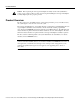
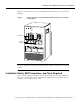
Product Overview Caution Before replacing the card cage and backplane assembly, read the “Safety Guidelines” section on page 7. The specific procedures for removing and installing the card cage and backplane assembly might require two people to perform. Product Overview The Cisco 7513, Cisco 7513-MX, and Cisco 7576 card cage holds the processor modules used by the system. Figure 1 shows the rear view of the system. The card cage and backplane are one assembly.
Product Overview Figure 1 Cisco 7513, Cisco 7513-MX, and Cisco 7576—Rear-Panel View Blower module Cable-management bracket NO NO RM RM AL AL EN AB LE EJE EJE SLO SLO T0 T1 SLO SLO T0 T1 SLA MAS VE TE R SLA MAS VE TE R CT Card cage and processor modules CT SLA SLA VE VE /M /M AS AS TE TE R CP U R CP U HA LT RE SE EN SE T AB T AU LE AU X. X.
Product Overview Note To provide a viewable image, slot numbers 0, 1, 2, 11, and 12 are not shown in Figure 2. The slot numbering scheme uses color coding to assist in identifying routers and CyBus assignments. Refer to the “Identifying Cisco 7576 Independent Routers and CyBuses” section in the Cisco 7500 Series Installation and Configuration Guide for detailed information on the slot numbering scheme.
Installation Safety, ESD Precautions, and Tools Required Figure 4 shows the location of the Cisco 7576 dual arbiters and chassis interfaces on the rear of the backplane.
Installation Safety, ESD Precautions, and Tools Required Safety Warnings Safety warnings appear throughout this publication in procedures that, if performed incorrectly, may harm you. A warning symbol precedes each warning statement. Warning This warning symbol means danger. You are in a situation that could cause bodily injury. Before you work on any equipment, be aware of the hazards involved with electrical circuitry and be familiar with standard practices for preventing accidents.
Safety Guidelines Aviso Este símbolo de aviso indica perigo. Encontra-se numa situação que lhe poderá causar danos físicos. Antes de começar a trabalhar com qualquer equipamento, familiarize-se com os perigos relacionados com circuitos eléctricos, e com quaisquer práticas comuns que possam prevenir possíveis acidentes.
Installation Safety, ESD Precautions, and Tools Required In addition, use the guidelines that follow when working with any equipment that is connected to telephone wiring or other network cabling: • • Never install telephone wiring during a lightning storm. • Never touch uninsulated telephone wires or terminals unless the telephone line is disconnected at the network interface. • Use caution when installing or modifying telephone lines.
Removing and Replacing Processor Modules Removing and Replacing Processor Modules Before you can replace the card cage and backplane assembly, you need to remove all processor modules installed in the card cage, and then replace them after the new card cage assembly is in place. The term processor module refers to the RSP2, RSP4, or RSP8 and all interface processors. Note Always use the ejector levers when installing or removing processor modules.
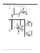
Removing and Replacing Processor Modules Figure 5 Ejector Levers and Captive Installation Screws Bottom ejector lever a Processor module slot Processor module carrier guide Captive installation screw c b H1482a Stop immediately on contact 10 Cisco 7513, Cisco 7513-MX, and Cisco 7576 Card Cage and Backplane Assembly Replacement Instructions
Replacing Processor Modules Board Rack with Processor Modules H3589 Figure 6 Caution To prevent damage to the processor modules, do not stack them on top of each other. Replacing Processor Modules You can replace an interface processor in any of the 11 interface processor slots, 0 through 5, and 8 through 12, from left to right. (See Figure 1.) slot 6 and slot 7 are reserved for the RSP.
Removing Power Supplies Caution Always install blank processor module fillers in empty processor slots to maintain the proper flow of cooling air through the chassis. Step 7 Use a screwdriver to tighten both captive installation screws on each processor module. Step 8 Attach network interface cables or other devices to the interface ports. Use the notes you made in the “Port and Slot Configuration Worksheet” section on page 23.
Removing Power Supplies Disconnect the power supply cables from the power supplies. Step 2 • For DC-input power supplies, refer to the configuration note 1200-Watt DC-Input Power Supply Replacement Instructions (Publication Number 78-1899-xx) that shipped with your Cisco 7513, Cisco 7513-MX, or Cisco 7576 chassis equipped with DC-input power supplies.
Removing the Old Card Cage and Backplane Assembly Caution To maintain agency compliance requirements and meet electromagnetic interference (EMI) emissions standards in a Cisco 7513 or Cisco 7576 chassis with a single power supply, the power supply blank must remain in the power supply bay adjacent to the power supply. (See Figure 10.) Replace this blank in the chassis after you replace the card cage assembly. To prevent system problems, do not mix AC-input and DC-input power supplies in the same chassis.
Removing the Old Card Cage and Backplane Assembly To remove the card cage and backplane assembly, follow these steps: Step 1 Turn the power switch on each power supply to the off position (O). Step 2 Disconnect the power supplies. • For DC-input power supplies, refer to the configuration note 1200-Watt DC-Input Power Supply Replacement Instructions (Publication Number 78-1899-xx) that shipped with your Cisco 7513, Cisco 7513-MX, or Cisco 7576 chassis equipped with DC-input power supplies.
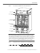
Exchanging the EEPROM Devices Figure 11 Removing the Card Cage and Backplane Assembly Captive screw Captive screw Card cage side flange Card cage side flange Captive screw Captive screw Air intake grill POWER A POWER H3096 B Step 6 With the captive screws loosened, carefully pull the card cage and backplane assembly straight out of the chassis until the entire assembly is clear of the chassis sides. (See Figure 11.) The assembly is not heavy but might be awkward to handle.
Exchanging the EEPROM Devices Caution The new EEPROM device(s) that shipped on your new card cage are blank. Note Do not perform these steps if you are upgrading a Cisco 7513 to a Cisco 7576. These instructions apply only to the replacement of an equivalent card cage.
Installing the New Card Cage and Backplane Assembly Figure 13 Location of the EEPROM Devices on the Rear of the Card Cage (Cisco 7576) EEPROM B Chassis interface board A 15271 Chassis interface board B EEPROM A EEPROM device Pin 1 Note The Cisco 7576 features two routers on one backplane. These are designated router A and router B. The backplane of the Cisco 7576 includes two dual arbiters, two chassis interfaces, and two EEPROM devices.
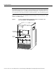
Installing the New Card Cage and Backplane Assembly Figure 14 Replacing the Card Cage and Backplane Assembly Captive screw Captive screw Card cage side flange Card cage side flange Captive screw Captive screw Air intake grill A POWER B H8819 POWER Caution The electronic components on the rear of the backplane are completely exposed when the card cage and backplane assembly is removed from the chassis. To prevent damaging these components, carefully slide the assembly into the chassis opening.
Replacing Power Supplies Replacing Power Supplies To replace the power supply, follow these steps: To replace a power supply, hold it as shown in Figure 15 and slide it into the power supply bay. Push the supply all the way into the chassis until the sides are flush against the chassis frame. (See Figure 16.) Do not jam the power supply into the power supply bay.
Checking the System Step 4 Repeat Step 1 through Step 3 for the second power supply if one is installed, or Step 1 and Step 2 for the power supply blank if one is present. Note After the AC power cable or DC power cable leads are reconnected to each power supply, reconnect the power cable at the power source. This completes the power supply replacement procedure. Checking the System To complete the installation, perform a final check of all connections, and then restart the system.
Checking the System Following is an example of this display: (display text omitted) GS Software (RSP-K), Version 10.3(571) Copyright (c) 1986-1995 by cisco Systems, Inc. Compiled Wed 10-May-95 25:12 RSP2 (Risc 4600) processor with 16384K bytes of memory. (display text omitted) Note The preceding Cisco IOS software display examples may differ depending on the router model and Cisco IOS software release being used.
Port and Slot Configuration Worksheet Port and Slot Configuration Worksheet The port and slot configuration worksheet (Table 1) is used with Figure 17 to assist in planning and documenting your use of the slots in a Cisco 7513, Cisco 7513-MX, or Cisco 7576 router. Figure 17 depicts the dual CyBus backplane, minus the time division multiplexing (TDM) connectors found on the Cisco 7576.
Port and Slot Configuration Worksheet Figure 17 Slot Numbering (Use with Table 1) SLOT 12 SLOT 11 SLOT 10 SLOT 9 SLOT 8 SLOT 5 SLOT 4 SLOT 3 SLOT 2 SLOT 1 SLOT 0 H3090 SLOT 7 SLOT 6 Cisco 7513 and Cisco 7513-MX Slot Assignments The dual CyBus backplane has 13 slots: interface processors are placed in slots 0 through 5 and 8 through 12. RSPs are placed in slots 6 and 7. Cisco 7576 Slot Assignments The Cisco 7576 consists of two independent routers on a single backplane.
Cisco Connection Online Cisco Connection Online Cisco Connection Online (CCO) is Cisco Systems’ primary, real-time support channel. Maintenance customers and partners can self-register on CCO to obtain additional information and services. Available 24 hours a day, 7 days a week, CCO provides a wealth of standard and value-added services to Cisco’s customers and business partners.
Documentation CD-ROM This document is to be used in conjunction with the Cisco 7500 Series Installation and Configuration Guide publication.