
Router Installation and Configuration Guide


3-15
Cisco 7204 Installation and Configuration Guide
OL-5101-02
Chapter 3 Installing the Cisco 7204
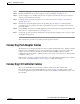
Connecting I/O Controller Cables
Figure 3-13 Console and Auxiliary Port Connections
Console Port Signals
Table 3-1 lists the signals used on the console port. The console port does not support modem control or
hardware flow control. Both Data Set Ready (DSR) and Data Carrier Detect (DCD) signals are active
when the system is running. The Request To Send (RTS) signal tracks the state of the Clear to Send
(CTS) input. The console port requires a straight-through EIA/TIA-232 cable.
Modem
Console terminal
H6539
MII
EN
RJ45
EN
RJ45
LINK
1O PWR
OK
R
J
-
4
5
C
P
U
R
E
S
E
T
FA
ST E
TH
ER
N
ET
IN
PU
T/O
U
TPU
T C
O
N
TR
O
LL
ER
ENABLED
PCMCIA
EJECT
SLOT 0
SLOT 1
FE MII
Auxiliary
port
Console
port
Table 3-1 Console Port Signals
Pin Signal Direction Description
1 GND – Ground
2TxD <— Transmit Data
3RxD —> Receive Data
6DSR —> Data Set Ready (always on)
7 GND – Ground
8DCD —> Data Carrier Detect (always on)