
Router Installation and Configuration Guide


(DRAFT LABEL) ALPHA DRAFT - CISCO CONFIDENTIAL
3-12
Cisco 7204 Installation and Configuration Guide
OL-5101-02
Chapter 3 Installing the Cisco 7204
Providing a Chassis Ground Connection for the Router Chassis
Note Older Cisco 7204 router chassis do not have the grounding receptacles.
To ensure the chassis grounding connection that you provide is adequate, you will need the following
parts and tools:
• 1 grounding lug—Must have two number-10 screw holes that have a 0.63-inch (16.002-mm) spacing
between them, and a wire receptacle large enough to accept a 6-AWG multistrand, copper wire. (See
Figure 3-11.) This grounding lug is not available from Cisco Systems; electrical-connector vendors
provide this type of grounding lug.
• 2 Phillips-head machine screws with locking washers—M5 (metric), 0.031-inch (0.8-mm) pitch,
0.315-inch (8-mm) length. These screws are not available from Cisco Systems; they are available
from any commercial hardware vendor.
• 1 grounding wire—6 AWG, 0.162-inch (4.115-mm) diameter, with approximately 0.108-inch
(2.743-mm) insulation, for a total wire diameter of approximately 0.27 inches (6.858 mm). The
wire’s length is dependent on your router location and site environment. This wire is not available
from Cisco Systems; it is available from any commercial cable vendor.
• Number 2 Phillips screwdriver.
• Crimping tool large enough to accommodate the diameter of the wire receptacle on your grounding
lug.
• Wire stripping tool.
Use the following procedure to attach the grounding lug to the chassis grounding receptacles on your
router chassis:
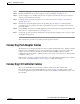
Figure 3-11 Attaching a Grounding Lug to the Chassis Grounding Receptacles
H10749
Grounding lug
Wire
Chassis
grounding
receptacles
Screws