
Router Installation and Configuration Guide


1-16
Cisco 7204 Installation and Configuration Guide
OL-5101-02
Chapter 1 Product Overview
Physical Description
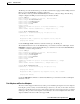
Note The I/O controller without the Fast Ethernet port does not have the FE enabled LED and the FE link LED.
The I/O controller without the Fast Ethernet port and the I/O controller that is equipped with a single
MII port do not have the MII enabled, RJ-45 enabled, and RJ-45 link LEDs.
Note An MII LINK LED is not provided on the I/O controller because the LED is provided on external
transceivers that are required for connecting to the MII port on the I/O controller. Refer to the section
“Fast Ethernet Connection Equipment” section on page 3-16 inChapter 3, “Installing the Cisco 7204”
for Fast Ethernet MII connection requirements.
Use the show diag 0 command to identify the I/O controller (with or without the Fast Ethernet port)
installed in your Cisco 7204 router.
Note Slot 0 in Cisco 7200 series routers is always reserved for the Fast Ethernet port on the I/O controller—if
present. If the I/O controller without the Fast Ethernet port is installed in your Cisco 7200 series router,
the system software will not display output for the show diag 0 command.
Note Refer to the section ““Port Adapter Slot and Logical Interface Numbering” section on page 1-23 for
information about port adapter slot numbering and logical interface numbering for the Cisco 7204 router.
The following sample output from the show diag 0 command is from a Cisco 7204 I/O controller with
the Fast Ethernet port that is equipped with an MII port and RJ-45 port:
Router> show diag 0
Slot 0:
Fast-ethernet on C7200 I/O with MII or RJ45 port adapter, 1 port
Port adapter is analyzed
Port adapter insertion time 00:10:42 ago
Hardware revision 2.0 Board revision A0
Serial number 3511336 Part number 73-1537-03
Test history 0x0 RMA number 00-00-00
EEPROM format version 1
EEPROM contents (hex):
0x20: 01 14 02 00 00 35 94 28 49 06 01 03 00 00 00 00
0x30: 50 0000 00 FF FF FF FF FF FF FF FF FF FF FF FF
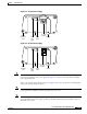
RJ45 LINK Indicates that the Fast Ethernet port’s RJ-45 port has established a valid link
with the network. This LED remains off during normal operation of the
router, unless there is an incoming carrier signal.
Slot 0 Slot 1 Goes on to indicate which PCMCIA slot is in use when either slot is being
accessed by the system. These LEDs remain off during normal operation of
the router.
Table 1-5 I/O Controller LEDs (continued)
LED Function