
Router Quick Start Guide


40
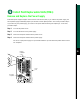
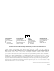
For the DC-input power supply: Use a screwdriver to loosen the captive installation screws on the
terminal block cover, lift the cover, use the wire cutters to cut the nylon strain-relief ties, and then
remove the three power leads (remove the ground lead last) from the terminal block.
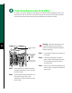
Install Field Replaceable Units (FRUs)
Step 5 Use a screwdriver to loosen and remove
thecaptive installationscrewonthetop of
the power supply.
Step 6 Grasp the power supply handle with one
hand and place your other hand
underneath to support the bottom of the
power supply.
O
T SHIP WITH POWER SUPPLY
A
LLED
FASTENER TO BE FULLY ENGAGED
BEFORE OPERATING POWER SUPPLY
INPUT VOLTAGE : 40-72 V=
INPUT CURRENT : 24-13A
Captive installati
o
screw
Power leads atta
c
to terminal block
( ) negative
( ) positive
( ) ground
H2530
Nylon ties on cab
and metal bracke
Warning Keep hands and fingers out of
the power supply bays. High voltage is
present on the power backplane when the
system is operating.
Step 7 Pull the power supply out of the bay and
put it aside.
Step 8 If the power supply bay is to remain
empty, install a power-supply filler plate
over the opening and secure it with a
mounting screw.
Step 9 Refer to the “Install Power Supplies in the
Router” section on page 11 to replace the
power supply.