
Router Quick Start Guide

11
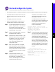
Install Power Supplies in the Router
Install the Hardware
0
I
OK
OK
FAIL
DC
FAN
OUTPUT
53427
POWER
B
POWER
A
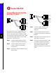
Captive screws
0
I
OK
OK
FAIL
AC
FAN
OUTPUT
0
I
OK
OK
FAIL
AC
FAN
OUTPUT
A
B
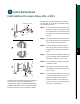
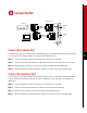
Note The Cisco 7513 and the Cisco 7576 routers
are shipped with the power supplies removed. Each
chassis comes with one power supply as standard
equipment; a second power supply is optional
equipment. The power supplies rest on the floor of
the chassis under the card cage assembly.
This procedure applies to AC-input and DC-input
power supplies, with differences clearly noted. Do
not mix AC-input and DC-input power supplies in
the same chassis. Install the first power supply in the
lowerpowersupply bay and thesecond, if any,inthe
upper bay. In systems with dual power supplies and
separate available power sources, connect each
power supply to separate input lines—the second
powersourcewilllikely be available duringafailure.
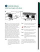
Step 1 For AC-input power supplies, confirm
that the power on the power supply is off.
For DC-input powersupplies, turnoff the
circuit breaker to which you will connect
power, and tape the breaker switch to the
off position.
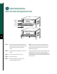
Step 2 Hold the power supply by the handle and
place your other hand underneath it.
Caution Use two hands to remove and
install power supplies.
Step 3 Place the powersupply insidethebay, and
align it to go straight into the bay.
Step 4 Push the power supply back into the bay
until its front panel is flush with the
chassis rear panel.
Step 5 Use a screwdriver to tighten the captive
installation screw on the top of the power
supply.
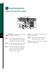
For AC-input power supplies, proceed to the
“Connect AC-Input Power Supply” section on
page 12. For DC-input power supplies, proceed to
the “Connect DC-Input Power Supply” section on
page 13.