Quick Start Guide Is Cisco documentation helpful? Click here or go to http://www.cisco.com/warp/public/732/docsurvey/rtg/ to give us your feedback.
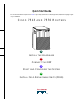
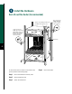
Install the Hardware Blower module Cable-management bracket Card cage and processor modules Interface processor slot numbering scheme Air intake vent Power supplies NO RM AL NO RM AL EN AB LE EJ EC T SL SLOT OT 0 1 SL MAST AV E ER SL MAST AV E ER SL AV E/M AS TE R CP U HA LT RE SE T SL AV E/M AS TE R CP U HA LT RE SE T AU X. AU X.
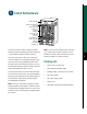
Install the Hardware Prepare to Install the Router Note For detailed hardware installation instructions and safety guidelines, refer to the Cisco 7500 Series Router Installation and Configuration Guide, Site Preparation and Safety Guide, and the Cisco 7500 Regulatory Compliance and Safety Guide.
Install the Hardware Install the Router on a Bench or Tabletop POWER A POWER H3118 B 3 Note To rack-mount the router, refer to the Warning When lifting the router, do not “Rack-Mount the Router (Recommended)” section on page 4. lift by grasping the handle of the blower module, nor should you grasp the air intake grill. Caution Two people are required to perform this step. Avoid sudden twists or moves to prevent injury.
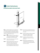
Install the Hardware Rack-Mount the Router (Recommended) M4 x 10-mm long Phillips flat-head screws (to attach ears to chassis) Chassis ear (cutaway of frame post to enable view of chassis ear) 10-32 x 5/8 in. long Phillips pan-head screws with integral square cone washers (for mounting brackets and chassis ears to rack posts) Bracket (2) 4 POWER A B To rack-mount the Cisco 7513 or Cisco 7576 router, you will perform the following steps: Step 1 Mount the brackets to the rack posts.
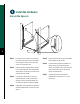
Install the Hardware Mount Brackets to the Rack Posts Rack post Flange ide ds lde 53382 ie Sh 5 Note The distance between the inner edges of the left and right rack-mounting posts must be at least 17.72 inches (45.088 cm), and the distance between the holes in the mounting posts must be 18.31 inches (46.5 cm) (+ .063 inches or .16 cm). Step 1 Step 2 Step 3 Place the bracket on the inner side of the rack post, with the flanged front edge of the bracket in front of the rack post.
Install the Hardware Secure the Spacers A C 53425 B 6 Step 1 Step 2 Loosen the 10-32 x 5/8-inch LG Phillips pan-head screw at the end of the ledge of the right-side bracket. This screw is the anchor for the spanner bar. Remove the tape that secures the spanner bar on the left bracket, and swing the bar down (see A) over the anchor screw on the opposite bracket (see B).
Install the Hardware Attach the Chassis Ears Center-mount position Flush-mount position H3174 7 POWER A POWER B Step 1 Position the ears on the chassis as follows: • To flush-mount the chassis, place each ear so that the mounting strips are flush with the end of the chassis, and align the mounting holes in the ear with those in the chassis.
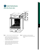
Install the Hardware Mount the Chassis in the Rack POWER A POWER B 53487 8 Caution Two people are required to Step 4 Slide the chassis back into the rack along the ledges until the ears meet the front mounting posts on both sides of the rack. Step 5 Secure each ear to the rack-mounting post with two 10-32 x 5/8-inch LG Phillips pan-head screws. perform this step.
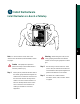
Install the Hardware Install Interface Processors, Fillers, VIPs, or RSPs processor slots, which are numbered 0 through 5, and 8 through 12, from left to right when viewing the chassis from the rear. Bottom ejector lever A Captive installation screw Card carrier guide Step 1 Hold the interface processor, filler, VIP, or RSP with one hand, and place your other hand under the carrier to support the card and guide it into the slot. Avoid touching the card.
Install the Hardware Attach the Cable-Management Bracket Blower module Loosen screws (2) Bracket Card cage H3120 10 Step 1 Locate the two slotted screws between the blower module and the card cage opening at the interface processor end of the router. Note If you are using very thin cables that slip Step 2 Use a flat-blade screwdriver to loosen the screws. Step 3 Place the bracket over the screws. Step 4 Tighten the screws. It may be necessary to bundle longer cables to avoid tangling them.
Install the Hardware Install Power Supplies in the Router A B DC FAN OUTPUT OK OK FAIL AC OK FAN OUTPUT OK AC FAIL OK FAN OUTPUT OK FAIL POWER A POWER I B I 0 I 0 Captive screws Note The Cisco 7513 and the Cisco 7576 routers Step 2 are shipped with the power supplies removed. Each chassis comes with one power supply as standard equipment; a second power supply is optional equipment. The power supplies rest on the floor of the chassis under the card cage assembly.
Install the Hardware Connect AC-Input Power Supply Cable-retention clip AC OK FAN OK OUTPUT FAIL AC OK FAN OK OUTPUT FAIL POWER B I I 0 53486 0 Captive screws 12 Step 1 Warning The system power switch on the Note A power supply blank must remain in any power supply should be off. empty power supply bay. Step 4 For AC-input power supplies, push the cable retention clip away from the power receptacle and plug in the power cable.
Install the Hardware Connect DC-Input Power Supply 13 Warning The system power switch on the ly move DC-input power su with the terminal b cover removed Power leads attached to terminal block (+) Positive (–) Negative ( ) Ground DC FAN O OK OK power supply should be off. Step 1 Use a screwdriver to loosen and remove the terminal block cover screws. Step 2 Lift and remove the terminal block cover.
Step 5 Attach the ground wire to the ground terminals using the 8-mm nut driver. Step 6 Check the power supply’s wiring and color code to verify that it matches the wiring and color code at the DC source. Warning Incorrect wiring could create a dangerous shock hazard and could damage the power supply, power source, and chassis components. 14 Step 7 Replace the terminal block cover. Step 8 Reconnect the power cable at the power source.
Connect the RSP DB-25 female Modem Auxiliary port Console port DB-25 male RSP H3538 Console terminal Connect the Console Port The system console port on the RSP is a DB-25 receptacle DCE port for connecting a data terminal, which allows you to configure and manage the system. The console port is labeled Console. Step 1 Connect the console cable from the terminal to the console port on the RSP. Step 2 Check your terminal’s documentation to determine the baud rate of the terminal you will be using.
Connect the RSP Connect the Console and the Auxiliary Y-Cables AUXILIARY CONSOLE DB-25 H9720 DB-25 The console and auxiliary Y-cables allow you to simultaneously connect the console or auxiliary ports on two RSP2s, RSP4s, or RSP8s to a single console terminal or external auxiliary device. These are configured as system master and slave in RSP slots 6 and 7 in the Cisco 7513. Step 1 Connect the DB-25 female end of the Y-cable to the console terminal device.
Start and Configure the System Step 1 Check the following components to make sure they are secure: • Each interface processor is inserted all the way into its slot, and captive installation screws are tightened. • All interface cable connections are secured, and any Flash memory cards are secured in their PC slots. initialization, the indicators on each interface processor behave differently (most flash on and off). • The system power cable is connected.
Start and Configure the System Start a Basic Configuration Many privileged-level EXEC commands are used to set operating parameters. To enter the privileged-level: Step 1 Enter the enable command at the EXEC prompt (>), and then enter a privileged-level password, as follows: Router> enable Password: Router# Step 2 Enter the configure terminal command to enter configuration mode: Router# configure terminal Enter configuration commands, one per line. End with CNTL/Z.
Start and Configure the System Perform a Basic Configuration Using Setup Step 5 Note The router’s serial (WAN) cable should not be Configure AppleTalk? [no]: yes Multizone networks? [no]: yes Configure IPX? [no]: yes connected to the CSU/DSU unless you are planning to use AutoInstall. If you are using the console Y-cable that shipped with your router, use either of the two DB-25 male plug ends of the Y-cable. Step 1 Select the protocols supported on your interfaces.
Start and Configure the System Configure an Ethernet Interface Step 1 Step 3 To configure your system for an Ethernet LAN, respond to the prompts as follows, using your own IP address and subnet mask information: Enter yes to enable AppleTalk on this interface, to configure for extended AppleTalk networks, and then enter the cable range number.
Step 2 Determine which protocols you want to allow on the synchronous serial interface and enter the appropriate responses: Configure IP unnumbered on this interface? [no]: IP address for this interface: 1.1.1.20 Number of bits in subnet field [0]: Class A network is 1.0.0.0, 0 subnet bits; mask is 255.0.0.
Start and Configure the System Perform a Basic Configuration Using Configuration Mode Step 2 Enter the interface type slot/port command at the enable prompt to enter interface configuration mode, as follows: At the reboot, the following example appears: Any interface listed with OK? value "NO" does not have a valid configuration.
Install Field Replaceable Units (FRUs) Flash Memory Cards A Flash memory card that ships with your Cisco 7513 or Cisco 7576 contains the Cisco IOS software image to boot your router. You do not need to format it. The RSP has two PC Card slots—slot 0 and slot 1—into which you can install a Flash memory card. In the RSP2, RSP4, and RSP8, the orientation is vertical. PC Card slot 0 is on the left and slot 1 is on the right (as shown).
Install Field Replaceable Units (FRUs) Format a Flash Memory Card Flash memory cards shipped as spare parts must be formatted. Use only Intel Series 2+ Flash memory cards. Step 1 Enter format slot0: (or format slot1:) to format the Flash memory card, as follows: Router# format slot0: Step 2 At the erase all sectors prompt, press Enter to proceed.
Install Field Replaceable Units (FRUs) Make a Flash Memory Card Image Bootable Note In this example, the filename is new.image, and the Flash memory card is located in slot 0. Step 1 Enter the configure terminal command at the enable prompt, as follows: Router# configure terminal Step 2 Enter the no boot system command, as follows. Router(config)# no boot system Step 3 Enter the boot system flash slot0:new.image command, as follows: Router(config)# boot system flash slot0:new.
Install Field Replaceable Units (FRUs) Prepare to Remove and Install an RSP To remove and install an RSP, you will perform the following steps: 26 • Copy the configuration file using a Trivial File Transfer Protocol (TFTP) server • Remove the RSP • Install the RSP • Connect to the RSP • Turn the system power back on, if it has been turned off • Retrieve the configuration file • Configure high system availability (HSA) or high availability (HA) features, provided you are using two RSPs (Follow
Install Field Replaceable Units (FRUs) Remove and Install an Interface Processor, Filler, VIP, or RSP Note Do not shut down the system power when removing an interface processor, VIP, or an RSP in a system configured for HA. If you are removing an RSP and have only one RSP, shut down the system, but first copy the configuration file to a TFTP server. See the “Copy the Configuration File for an RSP” section on page 31.
Install Field Replaceable Units (FRUs) Step 8 If you have a VIP4 and are using HSA with an RSP2 as the slave processor, wait 20-30 seconds, and then reinsert the RSP2. Step 9 Repeat Step 2 through Step 8 to remove any additional interface processors, fillers, VIPs, or RSPs. Step 5 In systems with a second RSP installed (and HSA or HA configured), use the show version command to verify that the slave (or standby) RSP is recognized by the system.
Install Field Replaceable Units (FRUs) Check the Interface Processor or VIP Installation If the enabled LED on a port adapter fails to go on, the interface processor or VIP may not be fully seated in the backplane. Refer to Appendix A in the Cisco 7500 Series Installation and Configuration Guide. Note When a new VIP is inserted or when a VIP is moved to a new slot, the system recognizes the new interfaces, but leaves them in the shutdown state until you configure them.
Step 5 30 When the interfaces are up, check the activity of each interface by observing the status LEDs, which are described in the LED section of your port adapter documentation.
Install Field Replaceable Units (FRUs) Step 3 Enter the show running-config command to display the currently running configuration on the terminal and ensure that the configuration information is complete and correct. If it is not, use the configure command to add or modify the existing configuration. Before you copy (save) the running configuration to a TFTP file server, ensure the following: Step 4 Create a file on the TFTP server.
Install Field Replaceable Units (FRUs) Step 7 Enter the name of the configuration file. The default is to use the name of the router with the suffix -confg. Press Return to accept the default filename, or enter a different name for the file, then press Return. In the following example, the default is accepted: Name of configuration file to write [Router-confg]? Write file Router-confg on host 1.1.1.1? [confirm] Writing Router-confg .....
Install Field Replaceable Units (FRUs) Retrieve the Configuration File for RSPs Retrieve the saved configuration and copy it to NVRAM by accessing the router through a console terminal, or from a remote terminal. Step 1 Enter the enable command at the EXEC prompt (>), and then enter a privileged-level password, as follows: Router> enable Password: Router# Note The router runs from the default configuration in NVRAM until the previous configuration is retrieved.
Install Field Replaceable Units (FRUs) The console display indicates whether or not the operation was successful. A series of exclamation points (!!!!) and [OK] (as shown in the preceding example) indicates that the operation was successful. A series of periods (. . .) and [timed out] or [failed] indicates a failure due to a network fault or an incorrect server name, address, or filename. The following is an example of a failed attempt to boot from a remote server: Booting Router-confg .....
Install Field Replaceable Units (FRUs) Remove and Install Port Adapters
A Screw
Note First remove the VIP from the chassis before removing the port adapter from the VIP. See the “Remove and Install an Interface Processor, Filler, VIP, or RSP” section on page 27 for instructions. 38 Step 1 Remove the screw that secures the port adapter (or blank port adapter), as shown in A. Step 2 Grasp the handle and carefully pull it out of its slot, away from the edge connector at the rear of the slot. (See A.
Install Field Replaceable Units (FRUs) Remove and Replace the Power Supply Redundant power supplies support online insertion and removal (OIR); if you remove one power supply, the second power supply immediately ramps up to maintain uninterrupted operation. In this case, proceed to Step 2. If you have only one power supply, you must turn off power before removing and replacing it. In this case, proceed to Step 1. Step 1 Turn off the power source. Step 2 Turn off the switch on the power supply.
Install Field Replaceable Units (FRUs) For the DC-input power supply: Use a screwdriver to loosen the captive installation screws on the terminal block cover, lift the cover, use the wire cutters to cut the nylon strain-relief ties, and then remove the three power leads (remove the ground lead last) from the terminal block.
41
Corporate Headquarters Cisco Systems, Inc. 170 West Tasman Drive San Jose, CA 95134-1706 USA http://www.cisco.com Tel: 408 526-4000 800 553-NETS (6387) Fax: 408 526-4100 European Headquarters Cisco Systems Europe 11, Rue Camille Desmoulins 92782 Issy Les Moulineaux Cedex 9 France http://www-europe.cisco.com Tel: 33 1 58 04 60 00 Fax: 33 1 58 04 61 00 Americas Headquarters Cisco Systems, Inc. 170 West Tasman Drive San Jose, CA 95134-1706 USA http://www.cisco.