
Network Router User Manual


5/26/05 Adding Cisco 1000 Series Lightweight Access Points to Floor Plan and Open
Area Maps
OL-7426-03
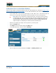
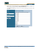
• Click OK to have the Cisco WCS User Interface add the Cisco 1000 Series lightweight access
points to the map and display the Position Access Points map similar to the following:
Note that the Cisco 1000 Series lightweight access point icons appear in the upper left area of
the map.
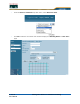
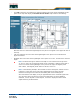
• Left-click and drag the Cisco 1000 Series lightweight access point icons to indicate their
physical locations.
• Highlight each Cisco 1000 Series lightweight access point icon in turn, and select the Antenna
Angle.
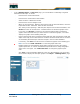
Note: The Antenna Angle is relative to the Map “X” axis. Because the origin of the
“X” and “Y” axes is at the upper left hand corner of the Map, 0 degrees points Side A
of the Cisco 1000 Series lightweight access point to the right, 90 degrees points
Side A down, 180 degrees points Side A to the left, and so on.
Note: In the following example, AP1 and AP3 are set to 90 degrees, and AP2 is set to
0 degrees, so the three Cisco 1000 Series lightweight access points provide
maximum coverage for the inside of the building and not the loading dock.
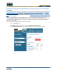
Also note that the first display is only an approximation of the actual RF signal inten-
sity, because it does not take into account the attenuation of various building
materials, such as drywall or metal objects, nor does it display the effects of RF
signals bouncing off obstructions.