PA-4T+ Synchronous Serial Port Adapter Installation and Configuration Product Number: PA-4T+(=) Platforms Supported: Cisco 7200 Series, Cisco 7000 Series and Cisco 7500 Series with VIP2, Cisco uBR7200 Series, Cisco 7100 Series Note If you ordered this port adapter as a spare, for your convenience Cisco has included a port adapter installation and configuration note for the Catalyst 5000 series Route Switch Module/Versatile Interface Processor 2 (RSM/VIP2).
Access Registrar, AccessPath, Any to Any, AtmDirector, CCDA, CCDE, CCDP, CCIE, CCNA, CCNP, CCSI, CD-PAC, the Cisco logo, Cisco Certified Internetwork Expert logo, CiscoLink, the Cisco Management Connection logo, the Cisco NetWorks logo, the Cisco Powered Network logo, Cisco Systems Capital, the Cisco Systems Capital logo, Cisco Systems Networking Academy, the Cisco Technologies logo, ControlStream, Fast Step, FireRunner, GigaStack, IGX, JumpStart, Kernel Proxy, MGX, Natural Network Viewer, NetSonar, Network
C H A P TER 1 Overview This chapter describes the PA-4T+ port adapter and describes its LEDs, cables, and receptacles. This chapter contains the following sections: • • • • • Port Adapter Overview, page 1-1 Synchronous Serial Overview, page 1-3 Serial Interface Specifications, page 1-4 Cables and Pinouts, page 1-5 LEDs, page 1-15 Port Adapter Overview The PA-4T+ provides the following electrical interfaces: EIA/TIA-232, EIA/TIA-449, EIA-530. X.21, and V.35.
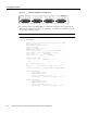
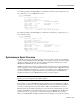
Port Adapter Overview Figure 1-2 PA-4T Port Adapter—Faceplate View H4496 RC LB CD RD TC TD LB CD RC RD TC TD RC LB CD RD TC TD RC LB CD RD TC TD EN FAST SERIAL The following example of the show diag slot command shows a PA-4T+ in port adapter slot 0 (PA Bay 0) and a PA-4T in port adapter slot 1 (PA Bay 1) on a VIP2 that is in interface processor slot 3 in a Cisco 7500 series router. Note In the following examples, the PA-4T+ is displayed as Mx serial.
Synchronous Serial Overview The following example of the show diag slot command shows a PA-4T+ in port adapter slot 1 in a Cisco 7200 series or a cisco uBR7200 series router: Router# show diag 1 Slot 1: Mx serial port adapter, 4 ports Port adapter is analyzed Port adapter insertion time 02:19:52 ago Hardware revision 1.
Serial Interface Specifications EIA/TIA-449. Like EIA/TIA-449, EIA-530 refers to the electrical specifications of EIA/TIA-422 and EIA/TIA-423. The specification recommends a maximum speed of 2 Mbps. EIA-530 is used primarily in the United States. The V.35 interface is most commonly used in the United States and throughout Europe, and is recommended for speeds up to 48 kbps. The X.
Cables and Pinouts Table 1-1 Standards for Transmission Speed Versus Distance EIA/TIA-232 Distances EIA/TIA-449, X.21, V.35, EIA-530 Distances Rate (bps) Feet Meters Feet Meters 2400 200 60 4,100 1,250 4800 100 30 2,050 625 9600 50 15 1,025 312 19200 25 7.6 513 156 38400 12 3.7 256 78 56000 8.6 2.6 102 31 1544000 (T1) – – 50 15 Balanced drivers allow EIA/TIA-449 signals to travel greater distances than EIA/TIA-232.
Cables and Pinouts • EIA/TIA-449: DTE mode with a 37-pin D-shell plug (CAB-449MT=); DCE mode with a 37-pin D-shell receptacle (CAB-449C=). • V.35: DTE mode or DCE mode with a 34-pin Winchester-type V.35 plug (CAB-V35MT= or CAB-V35MC=); DTE mode or DCE mode with a 34-pin Winchester-type V.35 receptacle (CAB-V35FT= or CAB-V35FC=). Also available is a cable with a male DB-60 plug on the router end and a male DB-34 shielded plug on the network end (CAB-V35MTS=). • X.
PA-4T+ Receptacles and Cables EIA/TIA-232 Connections The router end of all EIA/TIA-232 adapter cables is a high-density 60-pin plug. The network end of the adapter cable is a standard 25-pin D-shell connector (known as a DB-25) that is commonly used for EIA/TIA-232 connections. Figure 1-4 shows the connectors at the network end of the adapter cable.
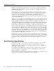
Cables and Pinouts EIA/TIA-449 Connections The router end of all EIA/TIA-449 adapter cables is a high-density 60-pin plug. The network end of the adapter cable provides a standard 37-pin D-shell connector, which is commonly used for EIA/TIA-449 connections. Figure 1-5 shows the connectors at the network end of the adapter cable. EIA/TIA-449 cables are available as either DTE (DB-37 plug) or DCE (DB-37 receptacle). Figure 1-5 EIA/TIA-449 Adapter Cable Connectors DCE H1344a DTE V.
PA-4T+ Port Adapter Cable Pinouts X.21 Connections The router end of all X.21 adapter cables is a high-density 60-pin plug. The network end of the adapter cable is a standard DB-15 connector. Figure 1-7 shows the connectors at the network end of the X.21 adapter cable. X.21 cables are available as either DTE (DB-15 plug) or DCE (DB-15 receptacle). Figure 1-7 X.21 Adapter Cable Connectors 1 8 15 DCE 9 H1346a DTE EIA-530 Connections The EIA-530 adapter cable is available in DTE mode only.
Cables and Pinouts Table 1-2 EIA/TIA-232 Adapter Cable Signals DTE Cable (CAB-232MT=) DCE Cable (CAB-232FC=) Router End, HD1 60-Position Plug Network End, DB-25 Plug Router End, HD 60-Position Plug Network End, DB-25 Receptacle Signal Pin Pin Signal Signal Pin Pin Signal Shield ground 46 1 Shield ground Shield ground 46 1 Shield ground TxD/RxD 41 —> 2 TxD RxD/TxD 36 <— 2 TxD RxD/TxD 36 <— 3 RxD TxD/RxD 41 —> 3 RxD RTS/CTS 42 —> 4 RTS CTS/RTS 35 <— 4 RTS
PA-4T+ Port Adapter Cable Pinouts Table 1-3 Intermediate Adapter Cable Signals (for Connecting a PA-4T+ to a NEC - NEXTSTAR 1E Model C4969 MD/SAC Unit) Router (DTE) End, DB-25 Receptacle Network (DCE) End, DB-25 Plug Signal Pin Pin Signal Shield ground 1 1 Shield ground TxD 2 —> 2 TxD RxD 3 <— 3 RxD RTS 4 —> 4 RTS CTS 5 <— 5 CTS DSR 6 <— 6 DSR Circuit ground 7 7 Circuit ground DCD 8 <— 8 DCD TxC, RxC 15, 17 <— 15 TxC – – <— 17 RxC LTST 18 —> 18 LT
Cables and Pinouts Table 1-4 EIA/TIA-449 Adapter Cable Signals DTE Cable (CAB-449MT=) DCE Cable (CAB-449C=) Router End, HD1 60-Position Plug Network End, DB-37 Plug Router End, HD 60-Position Plug Network End, DB-37 Receptacle Signal Pin Pin Signal Signal Pin Pin Signal Shield ground 46 1 Shield ground Shield ground 46 1 Shield ground TxD/RxD+ 11 —> 4 SD+ RxD/TxD+ 28 <— 4 SD+ TxD/RxD– 12 —> 22 SD– RxD/TxD– 27 <— 22 SD– TxC/RxC+ 24 <— 5 ST+ TxCE/TxC+ 13 —>
PA-4T+ Port Adapter Cable Pinouts Table 1-5 EIA-530 DTE Adapter Cable Signals (CAB-530MT=) Router End, HD1 60-Position Plug Network End, DB-25 Plug Signal Pin Pin Signal Shield ground 46 1 Shield ground TxD/RxD+ 11 —> 2 TxD+ TxD/RxD– 12 —> 14 TxD– RxD/TxD+ 28 <— 3 RxD+ RxD/TxD– 27 <— 16 RxC– RTS/CTS+ 9 —> 4 RTS+ RTS/CTS– 10 —> 19 RTS– CTS/RTS+ 1 <— 5 CTS+ CTS/RTS– 2 <— 13 CTS– DSR/DTR+ 3 <— 6 DSR+ DSR/DTR– 4 <— 22 DSR– DCD/DCD+ 5 <— 8 DCD+
Cables and Pinouts Table 1-6 V.
LEDs Table 1-7 X.
LEDs If any of the above conditions are not met, or if the initialization fails for other reasons, the enabled LED will not go on. Table 1-8 lists port LED status indications. Table 1-8 PA-4T+ Port LEDs LED Label Color State Function EN Green On Indicates ports are ready. TD Green On DTE—Transmit data out. DCE—Transmit data in. TC Green On DTE—Transmit clock in. DCE—Transmit clock in (TXCE). RD Green On DTE—Receive data in. DCE—Receive data out. RC Green On DTE—Receive clock in.
Preface This preface describes the objectives and organization of this document and explains how to find additional information on the PA-4T+ port adapter and other Cisco products and services.
Document Organization Document Organization This document is organized into the following chapters: Section Title Description Chapter 1 Overview Describes the PA-4T+ port adapter, illustrates their location in the supported hardware platforms, and describes its LED displays, cables, and receptacles. Chapter 2 Preparing for Installation Describes safety considerations, tools required, and procedures you should perform before the actual installation.
Cisco Connection Online • For hardware installation and maintenance information on the Cisco 7100 series routers, refer to the Cisco 7100 Series VPN Router Configuration Guide publication that shipped with your Cisco 7100 series router • For information on setting up a Virtual Private Network, see the Cisco 7100 Series VPN Configuration Guide.
Documentation CD-ROM You can access CCO in the following ways: WWW: http://www.cisco.com WWW: http://www-europe.cisco.com WWW: http://www-china.cisco.com Telnet: cco.cisco.com Modem: From North America, 408 526-8070; from Europe, 33 1 64 46 40 82. Use the following terminal settings: VT100 emulation; databits: 8; parity: none; stop bits: 1; and connection rates up to 28.8 kbps. For a copy of CCO’s Frequently Asked Questions (FAQ), contact cco-help@cisco.com.
C H A P TER 2 Preparing for Installation This chapter describes the general equipment, safety, and site preparation requirements for installing the PA-4T+ port adapter. • • • • Tools and Parts Required, page 2-1 Software and Hardware Requirements, page 2-2 Safety Guidelines, page 2-3 FCC Class B Compliance, page 2-5 Tools and Parts Required You need the following tools and parts to install a port adapter. If you need additional equipment, contact a service representative for ordering information.
Software and Hardware Requirements Software and Hardware Requirements lists the minimum Cisco IOS software release required to use the PA-4T+ port adapter in supported router platforms. Table 2-1 Router Platform PA-4T+ Software Requirements Recommended Minimum Cisco IOS Release Cisco 7000 series and Cisco 7500 series • With VIP2-15(=) or VIP2-40(=) Cisco IOS Release 11.1(8)CA or a later release of Cisco IOS Release 11.1 CA • With VIP2-50(=) Cisco IOS Release 11.
Software and Hardware Requirements Note The minimum recommended VIP2 model is a VIP2-15.
Safety Guidelines Safety Guidelines This section provides safety guidelines that you should follow when working with any equipment that connects to electrical power or telephone wiring. Safety Warnings Safety warnings appear throughout this publication in procedures that, if performed incorrectly, might harm you. A warning symbol precedes each warning statement. Warning This warning symbol means danger. You are in a situation that could cause bodily injury.
Electrical Equipment Guidelines Advarsel Dette varselsymbolet betyr fare. Du befinner deg i en situasjon som kan føre til personskade. Før du utfører arbeid på utstyr, må du vare oppmerksom på de faremomentene som elektriske kretser innebærer, samt gjøre deg kjent med vanlig praksis når det gjelder å unngå ulykker.
FCC Class B Compliance Preventing Electrostatic Discharge Damage Electrostatic discharge (ESD) damage, which can occur when electronic cards or components are improperly handled, results in complete or intermittent failures. Port adapters and processor modules comprise printed circuit boards that are fixed in metal carriers. Electromagnetic interference (EMI) shielding and connectors are integral components of the carrier.
FCC Class B Compliance • • Move the equipment farther away from the television or radio. Plug the equipment into an outlet that is on a different circuit from the television or radio. (That is, make certain the equipment and the television or radio are on circuits controlled by different circuit breakers or fuses.) Modifications to this product not authorized by Cisco Systems, Inc. could void the FCC approval and negate your authority to operate the product.
FCC Class B Compliance 2-8 PA-4T+ Synchronous Serial Port Adapter Installation and Configuration
C H A P TER 3 VIP2 and the PA-4T+ Port Adapter This chapter provides information on the PA-4T+ port adapter and its use in the VIP2 in Cisco 7000 series and Cisco 7500 series routers.
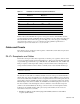
Installation Overview Figure 3-1 VIP2-15 or VIP2-40 with a PA-4T+ in Port Adapter Slot 1 Boot ROM CPU Bus connector U6 SRAM DIMM U5 U4 DRAM SIMMs U2 PA-4E in port adapter slot 0 PA-4T+ in port adapter slot 1 H9705 CD LB RC RD CD LB TC RC RD CD LB TC RC TD RD CD LB TD FAST SERIAL, ENHANCED TC ETHERNET-10BT RC K LIN 3 TD 1 0 EN 3 RD 2 TC 1 TD 0 2 Port adapter handles not shown Note Port adapters have a handle attached, but this handle is not shown to allow a full
Removing a Port Adapter Removing a Port Adapter This section provides the standard procedures for removing a port adapter on the VIP2. Depending on the circumstances, you might need to install a new port adapter on a VIP2 motherboard or replace a failed port adapter in the field.
Installing a Port Adapter Location of Port Adapter Screw—Partial Port Adapter View H3148 Figure 3-3 Screw Step 5 Remove the screw that secures the port adapter (or blank port adapter). Step 6 With the screw removed, grasp the handle on the front of the port adapter (or blank port adapter) and carefully pull it out of its slot, away from the edge connector at the rear of the slot. (See Figure 3-4.
Installing a Port Adapter Aligning a Port Adapter in a Port Adapter Slot H3150 Figure 3-5 Carrier Upper edge Lower edge Step 2 Before you insert the new port adapter in its slot, verify that the port adapter carrier is between the upper and lower slot edges, as shown in Figure 3-5. Do not jam the carrier between the slot edges.
Installing a Port Adapter Port Adapter Installed in a Port Adapter Slot—Partial Port Adapter View H3152 Figure 3-6 Step 4 Replace the screw in the rear of the port adapter slot. (See Figure 3-3 for its location.) Do not overtighten this screw. Step 5 Reinstall the VIP2 in the system. (Follow the steps in the section “Installing a VIP2” in the configuration note Second-Generation Versatile Interface Processor (VIP2) Installation and Configuration, which shipped with your VIP2.
C H A P TER 4 Cisco 7200 Series and the PA-4T+ Port Adapter This chapter provides information on the PA-4T+ and its use in the Cisco 7200 series routers. This chapter contains the following sections: • • • Installation Overview, page 4-1 Removing a Port Adapter, page 4-2 Installing a Port Adapter, page 4-3 Installation Overview Figure 4-1 shows a PA-4T+ installed in port adapter slot 1 of the Cisco 7206.
Removing a Port Adapter When a port adapter slot is not in use, a blank port adapter must fill the empty slot to allow the router to conform to EMI emissions requirements and to allow proper air flow across the port adapters. If you plan to install a new port adapter in a slot that is not in use, you must first remove a blank port adapter.
Installing a Port Adapter Figure 4-3 Handling a Port Adapter Metal carrier H6420 Printed circuit board Step 6 Place the port adapter on an antistatic surface with its components facing upward, or in a static shielding bag. If the port adapter will be returned to the factory, immediately place it in a static shielding bag. This completes the procedure for removing a port adapter from a Cisco 7200 series router.
Installing a Port Adapter Step 5 With the port adapter halfway in the slot, connect all required cables to the port adapter. Step 6 After connecting all required cables, carefully slide the port adapter all the way into the slot until the port adapter is seated in the router midplane. Step 7 After seating the port adapter in the router midplane, move the port adapter lever to the locked position. Figure 4-5 shows the port adapter lever in the locked position.
C H A P TER 5 Cisco uBR7200 Series and the PA-4T+ Port Adapter This chapter provides information on the PA-4T+ port adapter and its use on Cisco uBR7200 series universal broadband routers. This chapter includes the following sections: • • • Installation Overview, page 5-1 Removing a Port Adapter, page 5-2 Installing a Port Adapter, page 5-4 Installation Overview The PA-4T+ can be installed in any of the available port adapter slots in the Cisco uBR7200 series.
Removing a Port Adapter Note The Cisco uBR7200 series supports online insertion and removal (OIR); therefore, you do not have to power down the router when removing and replacing a PA-4T+. When a port adapter slot is not in use, blank port adapters must fill empty slots to allow the router to conform to EMI emissions requirements and to allow proper air flow across the port adapters. If you plan to install a new port adapter in a slot that is not in use, you must first remove the blank port adapter.
Removing a Port Adapter • Figure 5-3 For the Cisco uBR7223, place the port adapter lever in the unlocked position. (See Figure 5-3.) Placing the Port Adapter Lever in the Unlocked Position—Cisco uBR7223 Port adapter lever in unlocked position 16217 Port adapters Grasp the handle on the port adapter and pull the port adapter from the router midplane, about halfway out of its slot. If you are removing a blank port adapter, pull the blank port adapter completely out of the chassis slot.
Installing a Port Adapter Step 6 Place the port adapter on an antistatic surface with its components facing upward, or in a static shielding bag. If the port adapter will be returned to the factory, immediately place it in a static shielding bag. This completes the procedure for removing a port adapter from a Cisco uBR7200 series router.
Installing a Port Adapter Note If the retention clip does not slide up to the locked position, the port adapter is not completely seated in the midplane. Carefully pull the port adapter halfway out of the slot, reinsert it, and slide the port adapter lever up to the locked position.
Installing a Port Adapter This completes the procedure for installing a port adapter in a Cisco uBR7200 series router. Proceed to Chapter 7, “Installing the PA-4T+ Interface Cables,” to connect the necessary cables to your port adapter.
C H A P TER 6 Cisco 7100 Series and the PA-4T+ Port Adapter This chapter provides information on the PA-4T+ port adapter and its use in the Cisco 7100 series routers. This chapter contains the following sections: • • • Installation Overview, page 6-1 Removing a Port Adapter, page 6-2 Installing a Port Adapter, page 6-3 Installation Overview The PA-4T+ can be installed in port adapter slot 3 in the Cisco 7120 series, and in port adapter slot 4 in the Cisco 7140 series.
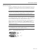
Removing a Port Adapter Figure 6-2 Cisco 7140 Series Router—Port Adapter Slot 4 Location Locked Unlocked ESD plug Slot 4 AC OK DC OK OTF SLOT 0 SLOT 1 PWR ACT ACT 0 FE 0 / 0 I EN RX RX 155 - MM TX EN CEL CAR ALM FE 0 / 1 RX LNK LNK 0 1 RX 155 - MM CONS AUX AC OK SYS RDY DC OK OTF TX CEL CAR ALM 2 7140 - 2MM3 22134 5 Depending on your circumstances, you might need to install a new port adapter in a Cisco 7100 series router or replace a failed port adapter in the field.
Installing a Port Adapter Figure 6-3 Handling a Port Adapter Metal carrier H6420 Printed circuit board Step 6 Place the port adapter on an antistatic surface with its components facing upward, or in a static shielding bag. If the port adapter will be returned to the factory, immediately place it in a static shielding bag.
Installing a Port Adapter Figure 6-4 Aligning the Single-Width Port Adapter Between the Slot Guides Guides I RCVR EN XMTR RCLK FERF RL FE 0 / 22132 5 AIS OOF LL Step 7 With the port adapter halfway in the slot, connect all required cables to the port adapter. Step 8 After connecting all required cables, carefully slide the port adapter all the way into the slot until the port adapter is seated in the router.
C H A P TER 7 Installing the PA-4T+ Interface Cables To continue your PA-4T+ port adapter installation, you must install the port adapter cables and configure the PA-4T+ interfaces. The instructions that follow apply to all supported platforms. Minor differences between the platforms are noted.
Replacing PA-4T+ Port Adapter Cables Caution Serial interface cables must be attached correctly or damage to the cable plug will result. Attempting to force a cable plug on the 60-pin receptacle can damage the plug. (See Figure 7-2.
Replacing PA-4T+ Port Adapter Cables Following is an example of the show controllers cbus command for a VIP2 that shows an interface port (3/1/0) that has an EIA/TIA-232 DTE cable attached: Router# show controllers cbus 3/1/0 slot3: VIP2, hw 2.3, sw 21.40, ccb 5800FF30, cmdq 48000088, vps 8192 software loaded from system IOS (tm) VIP Software (SVIP-DW-M), Version 11.1(8)CA, RELEASED SOFTWARE ROM Monitor version 17.0 Mx Serial(4), HW Revision 0x2, FW Revision 1.
Replacing PA-4T+ Port Adapter Cables For a Cisco 7100 series, Cisco 7200 series, or Cisco uBR7200 series router, use the following commands: Router# configure terminal Enter configuration commands, one per line. End with CNTL/Z. Router(config)# interface serial 1/0 Router(config-if)# no shutdown Ctrl-Z Router# Router# copy running-config startup-config For a VIP2, use the following commands: Router# configure terminal Enter configuration commands, one per line. End with CNTL/Z.
C H A P TER 8 Configuring the PA-4T+ Interfaces To continue your PA-4T+ port adapter installation, you must install the port adapter cables and configure the PA-4T+ interfaces. The instructions that follow apply to all supported platforms. Minor differences between the platforms are noted.
Identifying Port Adapter Slot and PA-4T+ Interface Port Numbers The system prompt for the privileged level ends with a pound sign (#) instead of an angle bracket (>). At the console terminal, use the following procedure to enter the privileged level: Step 1 At the user-level EXEC prompt, enter the enable command. The EXEC prompts you for a privileged-level password as follows: Router> enable Password: Step 2 Enter the password (the password is case-sensitive).
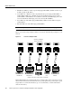
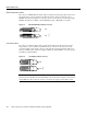
Cisco 7200 Series and Cisco uBR7200 Series Ports Figure 8-1 PA-4T+ Interface Port Address Example—Cisco uBR7246 3 2 1 5 0 6 TOKEN RING 4 K LIN 0 MII RJ4 EN AB LE D TX 2 RX 4 TX RX 3 TX 1 0 1 2 RX TX RX EN CD RX LB RC RD TC TD CD LB RC RD TC TD CD LB RC RD TC TD CD LB RC RD TC TX 3 2 3 1 0 2 1 0 D EN EN 3 AB LE LINK ETHERNET-10BFL FAST SERIAL, ENHANCED TD 5 FAST ETHERNET ETHERNET 10BT M II FE II M N E J-4 R EN 5 0 R PW J-4 K O K LIN
Identifying Port Adapter Slot and PA-4T+ Interface Port Numbers VIP2 Ports In the router, physical port addresses specify the actual physical location of each interface port on the router interface processor end. (See Figure 8-3.) This address is composed of a three-part number in the format interface processor slot number/port adapter number/interface port number.
Cisco 7100 Series Ports Cisco 7100 Series Ports In Cisco 7100 series routers, the slot number is the location in the chassis where the interface resides and the port number is the physical port. Interfaces in the Cisco IOS software are identified by a type, slot number, and port number. For example, serial 3/1 indicates port 1 on the serial port adapter in slot 3. Slots in Cisco 7120 series routers are numbered as shown in Figure 8-4.
Shutting Down an Interface Step 2 At the privileged-level prompt, enter configuration mode and specify that the console terminal will be the source of the configuration subcommands as follows: Router# configure terminal Enter configuration commands, one per line. End with CNTL/Z.
Shutting Down an Interface For a Cisco 7200 series, Cisco uBR7200 series, or Cisco 7100 series router, use the following example: Router# show interfaces serial 1/0 Serial 1/0 is administratively down, line protocol is down Hardware is M4T [display text omitted] For a VIP2, use the following example: Router# show interfaces serial 3/1/0 Serial 1/1/0 is administratively down, line protocol is down Hardware is cyBus Serial [display text omitted] Step 8 Reenable the interfaces.
Performing a Basic Configuration Performing a Basic Configuration Following are instructions for a basic interface configuration: enabling an interface, specifying IP routing, and setting up external timing on a DCE interface. You might also need to enter other configuration subcommands, depending on the requirements for your system configuration and the protocols you plan to route on the interface.
Configuring Timing (Clock) Signals Step 9 When you have included all of the configuration subcommands to complete the configuration, press Ctrl-Z (hold down the Control key while you press Z) or enter end to exit configuration mode and return to the EXEC command interpreter prompt. Step 10 Write the new configuration to nonvolatile memory as follows: Router# copy running-config startup-config [OK] Router# This completes the procedure for creating a basic configuration.
Configuring Timing (Clock) Signals Note Cisco IOS Release 11.2(7a)P or later, or 11.1(10)CA or later loaded on your Cisco 7200 series, Cisco 7000 series, or Cisco 7500 series router with a VIP2-40(=) support nonstandard clock rates (any value from 1200 to 8000000) on PA-4T+ interfaces. Cisco IOS Release 12.0(3)T or later, or 12.0(1)XE or later support nonstandard clock rates on PA-4T+ interfaces installed in Cisco 7204VXR and Cisco 7206VXR routers. Cisco IOS Release 11.
Setting the Clock Rate When the PA-4T+ interface is a DTE, the invert-txc command inverts the TxC signal it receives from the remote DCE. When the PA-4T+ interface is a DCE, this command inverts the clock signal to the remote DTE port. Use the no invert-txc command to change the clock signal back to its original phase.
Configuring Half-Duplex and Binary Synchronous Communications Configuring CRCs Cyclic redundancy check (CRC) is an error-checking technique that uses a calculated numeric value to detect errors in transmitted data. All interfaces use a 16-bit CRC (CRC-CITT) by default, but also support a 32-bit CRC. The sender of a data frame calculates the frame check sequence (FCS). Before it sends a frame, the sender appends the FCS value to the message.
Configuring Half-Duplex Configuring Half-Duplex Use the half-duplex command to configure PA-4T+ interfaces for half-duplex mode; full-duplex mode is the default for low-speed serial interfaces. Serial DCE interfaces in half-duplex mode can be configured for controlled-carrier mode or constant-carrier mode; constant-carrier mode is the default. Use the half-duplex controlled-carrier command to configure a PA-4T+ interface for controlled-carrier mode.
Checking the Configuration Table 8-1 Half-Duplex Timer Default Settings Timer Command Syntax Default Settings (Milliseconds) CTS delay half-duplex timer cts-delay 0 CTS drop timeout half-duplex timer cts-drop-timeout 250 DCD drop delay half-duplex timer dcd-drop-delay 100 DCD transmission start delay half-duplex timer dcd-txstart-delay 100 RTS drop delay half-duplex timer rts-drop-delay 3 RTS timeout half-duplex timer rts-timeout 3 Transmit delay half-duplex transmit-delay 0 Confi
Using show Commands to Display Interface Information Using show Commands to Display Interface Information To display information about a specific interface, use the show interfaces command with the interface type and port address in the format show interfaces [type slot/port] on a Cisco 7200 series, Cisco uBR7200 series, or Cisco 7100 series router, or show interfaces [type slot/port-adapter/port] on a VIP2. Note Output from the show interfaces command displays the PA-4T+ as M4T.
Checking the Configuration The following example of the show interfaces serial slot/port command on a Cisco 7200 series, Cisco uBR7200 series, or Cisco 7100 series router shows all of the information specific to the first PA-4T+ interface port (interface port 0) in port adapter slot 1: Router# show interfaces serial 1/0 Serial1/0 is up, line protocol is up Hardware is M4T Internet address is 10.10.10.
Using show Commands to Display Interface Information The show version (or show hardware) command displays the configuration of the system hardware (the number of each port adapter type installed), the software version, the names and sources of configuration files, and the boot images. Following is an example of the show version command: Router# show version Cisco Internetwork Operating System Software IOS (tm) 7200 Software (C7200-J-M), RELEASED VERSION 11.1(8)CA [sglee 108] Synced to mainline version: 11.
Checking the Configuration VIP2 show interfaces Command Following are examples of how the show interfaces [type slot/port-adapter/port] command displays status information (including the physical slot and port address) for the interfaces you specify. The four PA-4T+ interfaces (0–3) are in interface processor slot 3, in port adapter slot 1. Router# show interfaces serial 3/1/0 Serial3/1/0 is up, line protocol is up Hardware is cyBus Serial Internet address is 10.10.10.
Using show Commands to Display Interface Information The following example of the show interfaces serial slot/port-adapter/port command shows all of the information specific to the first PA-4T+ interface port (interface port 0) in port adapter slot 1: Router# show interfaces serial 3/1/0 Serial3/1/0 is up, line protocol is up Hardware is cyBus Serial Internet address is 10.10.10.
Checking the Configuration The show version (or show hardware) command displays the configuration of the system hardware (the number of each interface processor type installed), the software version, the names and sources of configuration files, and the boot images. Following is an example of the show version command used with a Cisco 7500 series router: Router# show version Cisco Internetwork Operating System Software IOS (tm) GS Software (image-name), Version 11.
Using ping and loopback Commands Use the show diag command to view all the interface types installed in your system.
Checking the Configuration Following is an example of a successful ping command to a remote server with the address 10.10.10.10: Router# ping 10.10.10.10 Type escape sequence to abort. Sending 5, 100-byte ICMP Echoes to 10.10.10.10, timeout is 2 seconds: !!!!! Success rate is 100 percent (5/5), round-trip min/avg/max = 1/15/64 ms Router# If the connection fails, verify that you have the correct IP address for the server and that the server is active (powered on), and repeat the ping command.