
Network Card User Manual

Overview 1-3
LEDs
Note You should replace older PA-2H port adapters with the newer PA-2H Rev. B port adapter.
Contact Cisco’s Technical Assistance Center (TAC) for replacement details. (For information on the
TAC, refer to the “Cisco Connection Online” section on page vi.)
LEDs
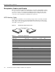
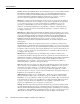
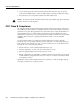
This section provides information on the LEDs on the faceplate of the HSSI port adapter. The HSSI
port adapter has two rows of five status LEDs, one row of five for each HSSI port on the port adapter
(TD, TC, RD, RC, and LB/C), and one enabled LED for the port adapter. (See Figure 1-4.)
Figure 1-4 LEDs on the HSSI Port Adapter (Partial Front View of PA-2H Shown)
After system initialization, the enabled LED, which is present on all interface processors, lights to
indicate that the port adapter has been enabled for operation.
The following conditions must be met before the HSSI port adapter is enabled:
• The port adapter contains a valid microcode version that has successfully been downloaded.
• The port adapter is correctly connected to the backplane and receiving power in Cisco 7000
series and Cisco 7500 series routers, the Catalyst 5000 family switches, or to the midplane and
receiving power in Cisco 7200 series and Cisco uBR7200 series routers.
• The bus recognizes the port adapter or HSSI-equipped VIP2 or Catalyst RSM/VIP2.
If any of these conditions is not met, or if the initialization fails for other reasons, the enabled LED
does not go on.
The five additional status LEDs on the HSSI port adapter indicate the following:
• TD—When on, the transmit data LED indicates that the port adapter has been detected by, and
is able to send packets to, the external DSU.
• TC—When on, the transmit clock LED indicates that the port adapter is transmitting a transmit
clock signal to the external DSU. During normal operation, this signal is derived from the RT
signal from the external DSU. During loopback, this signal is generated internally.
• RD—When on, the receive data LED indicates that the port adapter has detected, and is able to
receive packets from, the external DSU.
• RC—When on, the receive clock LED indicates that the port adapter has detected a Receive
Clock signal. During normal operation, this signal is received from the external DSU. During
loopback, this signal is generated internally.
• LB/C—When green, this dual-color, loopback/connected LED indicates normal operation which
means that the port adapter is properly connected to the external DSU and the TA (data terminal
equipment [DTE] Available) and CA (data communications equipment [DCE] Available) signals
are active. (See Table 1-1.) When yellow, this LED indicates that the port adapter is in loopback
(LB) mode or is otherwise not physically connected to the DSU. When off, the port is neither
connected or in loopback mode.
ENABLED
H7446
TD
TC
RD
RC
LB/C
0
1