PA-2H Dual-Port HSSI Port Adapter Installation and Configuration Product Numbers: PA-2H and PA-2H= Platforms Supported: Cisco 7200 Series (including a Cisco 7206 as a router shelf in a Cisco AS5800 Universal Access Server), Cisco 7000 Series and Cisco 7500 Series with VIP2, Cisco uBR7200 Series, and the Catalyst RSM/VIP2 on the Catalyst 5000 Family Switches Corporate Headquarters Cisco Systems, Inc. 170 West Tasman Drive San Jose, CA 95134-1706 USA http://www.cisco.
THE SPECIFICATIONS AND INFORMATION REGARDING THE PRODUCTS IN THIS MANUAL ARE SUBJECT TO CHANGE WITHOUT NOTICE. ALL STATEMENTS, INFORMATION, AND RECOMMENDATIONS IN THIS MANUAL ARE BELIEVED TO BE ACCURATE BUT ARE PRESENTED WITHOUT WARRANTY OF ANY KIND, EXPRESS OR IMPLIED. USERS MUST TAKE FULL RESPONSIBILITY FOR THEIR APPLICATION OF ANY PRODUCTS.
About This Manual This chapter explains the objectives and organization of the PA-2H Dual-Port HSSI Port Adapter Installation and Configuration document and defines the conventions used to convey instructions and information. Document Objectives This document describes the installation and configuration of the dual-port High-Speed Serial Interface (HSSI) port adapter (PA-H Rev.
Cisco Connection Online • Chapter 2, “Preparing for Installation,” is a preparatory chapter that describes safety considerations, tools required, and procedures you should perform before the actual installation. • Chapter 3, “VIP2 and the Dual-Port HSSI Port Adapter,” provides instructions for installing the PA-2H dual-port HSSI port adapter on a VIP2 interface processor installed in a Cisco 7500 or Cisco 7000 series router.
Documentation CD-ROM Note If you are a network administrator and need personal technical assistance with a Cisco product that is under warranty or covered by a maintenance contract, contact Cisco’s Technical Assistance Center (TAC) at 800 553-2447, 408 526-7209, or tac@cisco.com. To obtain general information about Cisco Systems, Cisco products, or upgrades, contact 800 553-6387, 408 526-7208, or cs-rep@cisco.com.
If You Need More Information — Second-Generation Versatile Interface Processor (VIP2) Installation and Configuration (for VIP2 users only) • For hardware installation and maintenance information on the Catalyst 5000 family switches and the Catalyst RSM/VIP2, refer to the following publications: — The installation and configuration guide that shipped with your Catalyst 5000 family switches — Route Switch Module Catalyst VIP2-15 and VIP2-40 Installation and Configuration Note (Document Number 78-4780-01) w
If You Need More Information • For general information about documentation, refer to the Documentation CD-ROM, the “Cisco Connection Online” section on page vi or call Customer Service at 800 553-6387 or 408 526-7208. Customer Service hours are 5:00 a.m. to 6:00 p.m. Pacific time, Monday through Friday (excluding Cisco-observed holidays). You can also send e-mail to cs-rep@cisco.
If You Need More Information x PA-2H Dual-Port HSSI Port Adapter Installation and Configuration
C H A P TER 1 Overview This chapter provides physical and functional overviews of the PA-2H dual-port high-speed serial interface (HSSI) port adapter. The chapter contains the following sections: • • • Port Adapter Overview, page 1-1 LEDs, page 1-3 Receptacles, Cables, and Pinouts, page 1-4 Port Adapter Overview The PA-2H dual-port HSSI port adapter provides two high-speed serial interfaces. (See Figure 1-1.) The interfaces on PA-2H are considered to be data terminal equipment (DTE) devices.
Port Adapter Overview The HSSI port adapter conforms to BABT/TC/130 and EIA/TIA-612 and EIA/TIA-613 standards for HSSI. PA-2H provides two interfaces. Each interface provides a full-duplex synchronous serial interface for transmitting and receiving data at rates of up to 52 megabits per second (Mbps). The HSSI, which was recently standardized as EIA/TIA 612/613, provides access to services at T3 (45 Mbps), E3 (34 Mbps), and Synchronous Optical Network (SONET) STS-1 (51.82 Mbps) rates.
LEDs Note You should replace older PA-2H port adapters with the newer PA-2H Rev. B port adapter. Contact Cisco’s Technical Assistance Center (TAC) for replacement details. (For information on the TAC, refer to the “Cisco Connection Online” section on page vi.) LEDs This section provides information on the LEDs on the faceplate of the HSSI port adapter.
Receptacles, Cables, and Pinouts Receptacles, Cables, and Pinouts This section provides information about the HSSI cables you should use with the HSSI port adapter. Two types of cables are available for use with the HSSI port adapter: the HSSI interface cable used to connect your router to an external DSU (and HSSI network) and a null modem cable, which allows you to connect two routers back to back.
HSSI Null Modem Cable HSSI Null Modem Cable The null modem cable (CAB-HNUL=) can connect two routers directly back to back. The null modem cable is 10-feet (3.048 meters) long. Figure 1-6 shows the null modem cable. The maximum null modem cable length allowed is 50 feet (15.24 meters). The two routers must be in the same location and can be two Cisco 7000 series routers, two Cisco 7500 series routers, two Cisco 7200 series routers, two Cisco uBR7200 series routers, or any combination of each.
Receptacles, Cables, and Pinouts 1-6 PA-2H Dual-Port HSSI Port Adapter Installation and Configuration
C H A P TER 2 Preparing for Installation This chapter describes the general equipment, safety, and site preparation requirements for installing the PA-2H dual-port high-speed serial interface (HSSI) port adapters. This chapter contains the following sections: • • • • List of Parts and Tools, page 2-1 Software and Hardware Requirements, page 2-2 Safety Guidelines, page 2-3 FCC Class B Compliance, page 2-6 List of Parts and Tools You need the following parts and tools to install a port adapter.
Software and Hardware Requirements Software and Hardware Requirements Table 2-1 lists the minimum Cisco IOS software release required to use the 2H port adapters in supported router platforms. Table 2-1 2H Port Adapter Software Requirements Platform Minimum Cisco IOS Release Cisco 7000 series and Cisco 7500 series • With VIP2-15(=) Cisco IOS Release 11.1(15)CA or a later release of Cisco IOS Release 11.1 CA • With VIP2-40(=) Cisco IOS Release 11.1(15)CA or a later release of Cisco IOS Release 11.
Safety Guidelines PA-2H cannot be used with a PA-A1 (Asynchronous Transfer Mode [ATM]) port adapter installed in the adjacent port adapter slot of your VIP2 or Catalyst RSM/VIP2. All other port adapters are compatible with PA-2H when installed in the adjacent port adapter slot of your VIP2 or Catalyst RSM/VIP2.
Safety Guidelines Varoitus Tämä varoitusmerkki merkitsee vaaraa. Olet tilanteessa, joka voi johtaa ruumiinvammaan. Ennen kuin työskentelet minkään laitteiston parissa, ota selvää sähkökytkentöihin liittyvistä vaaroista ja tavanomaisista onnettomuuksien ehkäisykeinoista. Tässä julkaisussa esiintyvien varoitusten käännökset löydät laitteen mukana olevasta Regulatory Compliance and Safety Information -kirjasesta (määräysten noudattaminen ja tietoa turvallisuudesta).
Electrical Equipment Guidelines Electrical Equipment Guidelines Follow these basic guidelines when working with any electrical equipment: • Before beginning any procedures requiring access to the chassis interior, locate the emergency power-off switch for the room in which you are working. • • Disconnect all power and external cables before moving a chassis. • Do not perform any action that creates a potential hazard to people or makes the equipment unsafe.
FCC Class B Compliance • Avoid contact between the printed circuit boards and clothing. The wrist strap only protects components from ESD voltages on the body; ESD voltages on clothing can still cause damage. • Never attempt to remove the printed circuit board from the metal carrier. Caution For safety, periodically check the resistance value of the antistatic strap. The measurement should be between 1 and 10 megohms.
C H A P TER 3 VIP2 and the Dual-Port HSSI Port Adapter This chapter describes the dual-port high-speed serial interface (HSSI) port adapter and its use on the VIP2 in Cisco 7200 series and Cisco 7500 series routers. Installation Overview The HSSI port adapter can be installed in either port adapter slot 0 or port adapter slot 1 on the VIP2. Figure 3-1 shows a VIP2 with PA-2H installed in port adapter slot 0.
Installation Overview Figure 3-2 shows two HSSI port adapters (PA-H Rev. B) installed in port adapter slots 0 and 1, on a VIP2-50.
Removing a Port Adapter When only one port adapter is installed on a VIP2, a blank port adapter must fill the empty slot to allow the VIP2 and router chassis to conform to electromagnetic interference (EMI) emissions requirements, and so that air flows through the chassis properly. If you plan to install a new port adapter, you must first remove the blank port adapter.
Installation Overview Pulling a Port Adapter Out of a Slot (Partial Port Adapter View) H3149 Figure 3-4 Step 7 If you removed a port adapter, place it in an antistatic container for safe storage or shipment back to the factory. If you removed a blank port adapter, no special handling is required; however, store the blank port adapter for potential future use. This completes the procedure for removing a port adapter from a VIP2.
Installing a Port Adapter Caution To prevent jamming the carrier between the upper and lower edges of the port adapter slot, and to assure that the edge connector at the rear of the port adapter seats in the connector at the rear of the port adapter slot, make certain that the leading edges of the carrier are between the upper and lower slot edges, as shown in the cutaway in Figure 3-5.
Installation Overview 3-6 PA-2H Dual-Port HSSI Port Adapter Installation and Configuration
C H A P TER 4 Catalyst RSM/VIP2 and the Dual-Port HSSI Port Adapter This chapter describes the dual-port high-speed serial interface (HSSI) port adapter and its use on the Catalyst RSM/VIP2 in the Catalyst 5000 family switches. Caution If you are using the HSSI dual-port adapter in the Catalyst 5000, 5500, 5505, or 5509 switch, you must install the port adapter on the Catalyst RSM/VIP2-15 or -40 Revision 2 (board part number 73-3468-XX, where XX is the version number).
Installation Overview Catalyst RSM/VIP2-40 with PA-2H in Port Adapter Slot 0 Standoff mounting hole Backplane bus connector Ribbon cables Standoff mounting holes Standoff mounting holes Port adapter securing screw Port adapter securing screw Port adapter blank in port adapter slot 1 Port adapter in slot 0 0 TD TC D R C R /C LB 0 1 HSSI CD D LE AB EN 1 26772 Figure 4-1 Note Port adapters have a handle attached, but this handle is not shown to allow a full view of detail on each por
Removing a Port Adapter Caution To prevent system problems, do not remove port adapters from the Catalyst RSM/VIP2 motherboard or attempt to install other port adapters on the Catalyst RSM/VIP2 motherboard, while the system is operating. To install or replace port adapters, first remove the Catalyst RSM/VIP2 from its interface processor slot. Caution To prevent interface reconfiguration requirements, we strongly recommend that you replace a port adapter with the same type of port adapter you removed.
Installation Overview Location of Port Adapter Screw (Partial Port Adapter View) H3148 Figure 4-2 Screw Step 6 Remove the screw that secures the port adapter (or blank port adapter). Step 7 With the screw removed, grasp the handle on the front of the port adapter (or blank port adapter) and carefully pull it out of its slot, away from the edge connector at the rear of the slot. (See Figure 4-3.
Installing a Port Adapter Installing a New Port Adapter H3150 Figure 4-4 Carrier Upper edge Lower edge Caution To prevent jamming the carrier between the upper and lower edges of the port adapter slot, and to assure that the edge connector at the rear of the port adapter seats in the connector at the rear of the port adapter slot, make certain that the leading edges of the carrier are between the upper and lower slot edges, as shown in the cutaway in Figure 4-4.
Installation Overview 4-6 PA-2H Dual-Port HSSI Port Adapter Installation and Configuration
C H A P TER 5 Cisco 7200 Series and the Dual-Port HSSI Port Adapter This chapter provides information specific to the dual-port high-speed serial interface (HSSI) port adapter and its use with Cisco 7200 series routers, which includes the Cisco 7206 as a router shelf in a Cisco AS5800 Universal Access Server. Installation Overview The HSSI port adapter can be installed in any of the available port adapter slots in Cisco 7200 series routers.
Installation Overview Depending on your circumstances, you might need to install a new port adapter in a Cisco 7200 series router or replace a failed port adapter in the field. In either case, no tools are necessary; all port adapters available for the Cisco 7200 series routers connect directly to the router midplane and are locked into position by a port adapter lever.
Replacing a Port Adapter Grasp the handle on the port adapter and pull the port adapter from the midplane, about half way out of its slot. If you are removing a blank port adapter, pull the blank port adapter from the port adapter slot. Step 3 Note As you disengage the port adapter from the router midplane, OIR administratively shuts down all active interfaces on the port adapter. Step 4 With the port adapter half way out of the slot, disconnect all cables from the port adapter.
Installation Overview Aligning the Port Adapter Metal Carrier Between the Slot Guides (Cisco 7206 shown) 2 1 0 6 3 TOKEN RING 5 FAST ETHERNET 4 K LIN MII 2 0 RJ4 5 D LE AB EN 3 3 LINK 1 2 3 0 2 1 0 ETHERNET 10BT EN AB LE D Slot guide H6597 Figure 5-4 ET C 45 O PW K R 1O M E II N R E J4 N 5 R L J4 IN 5 K T 0 T SL O EJ EC PC M C IA EN AB LE D R J- PU R ES M II FE SL O T 1 1 FAST ETHERNET INPUT/OUTPUT CONTROLLER Note: This adapter alignment applies to any
Replacing a Port Adapter Figure 5-5 Placing the Port Adapter Lever in the Locked Position (Cisco 7206 shown) 3 2 1 5 0 6 TOKEN RING FAST ETHERNET 4 RJ4 5 MII 0 LIN K D LE AB EN 3 2 3 LINK 1 0 2 1 0 EN 3 AB LE D ETHERNET 10BT 2 CD LB RC RD TC TD CD LB RC RD TC TD CD LB RC RD TC TD CD LB RC RD TC ET 0 D LE AB R E J4 N 5 1O O PW K R M E II N R L J4 IN 5 K T 0 EC O T SL EJ PC M C IA EN H6747 C 45 R J- FAST ETHERNET INPUT/OUTPUT CONTROLLER
Installation Overview 5-6 PA-2H Dual-Port HSSI Port Adapter Installation and Configuration
C H A P TER 6 Cisco uBR7200 Series and the Dual-Port HSSI Port Adapter This chapter provides information on the PA-2H dual-port high-speed serial interface (HSSI) port adapter and its use on the Cisco uBR7200 series routers. Installation Overview The HSSI port adapter is used in the Cisco uBR7200 series routers and can be installed in any of the available port adapter slots. Figure 6-1 shows an HSSI port adapter installed in port adapter slot 2 of a Cisco uBR7200 series router.
Installation Overview When a port adapter slot is not in use, a blank port adapter must fill the empty slot to allow the router to conform to EMI emissions requirements and to allow proper air flow across the port adapters. If you plan to install a new port adapter in a slot that is not in use, you must first remove a blank port adapter.
Removing a Port Adapter Figure 6-3 Placing the Port Adapter Lever in the Unlocked Position (Cisco uBR7223 Shown) Port adapters 16217 Port adapter lever in unlocked position Grasp the handle on the port adapter and pull the port adapter from the midplane, about half way out of its slot. If you are removing a blank port adapter, pull the blank port adapter from the chassis slot.
Installation Overview Replacing a Port Adapter Following is the procedure for installing a new port adapter in a Cisco uBR7200 series router: Step 1 Attach an ESD-preventative wrist strap between you and an unfinished chassis surface. Step 2 Use both hands to grasp the port adapter by its metal carrier edges and position the port adapter so that its components are downward. (Refer to Figure 6-4.
Replacing a Port Adapter Figure 6-6 Placing the Port Adapter Retention Clip in the Locked Position (Cisco uBR7246 Shown) H11517 Port adapters Port adapter retention clip in locked position For a Cisco uBR7223, place the port adapter lever in the locked position. (Refer to Figure 6-7.
Installation Overview 6-6 PA-2H Dual-Port HSSI Port Adapter Installation and Configuration
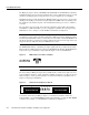
C H A P TER 7 Cable Installation and Interface Configuration To continue your dual-port high-speed serial interface (HSSI) port adapter installation, you must install the port adapter cables and configure the HSSI interfaces. The instructions that follow apply to all supported platforms. Minor differences between the platforms are noted. Attaching HSSI Port Adapter Interface Cables On a single HSSI port adapter, you can use up to two HSSI connections (on PA-2H).
Attaching a Null Modem Cable Connecting HSSI Cables (Front View—PA-2H Shown without Handle) HSSI Rev. B H10889 1 0 1 /C LB RC RD TC TD 0 EN AB LE D Figure 7-1 HSSI cables To T3, E3, or SONET DSU Step 2 Attach the network end of your HSSI cables to your T3, E3, or SONET DSU, or other external HSSI equipment. This completes the procedure for attaching HSSI cables to the HSSI port adapter.
Configuring the HSSI Interfaces Note In the Cisco 7206 and Cisco 7206VXR router shelves, you define interfaces by type and physical shelf/port adapter/port locations. For information on Cisco 7206 and Cisco 7206VXR router shelf physical port addresses, refer to the “Identifying Chassis Slot, Port Adapter Slot, and HSSI Interface Port Numbers” section on page 7-4.
Configuring the HSSI Interfaces • Whether the new interfaces will use bridging For a summary of the configuration options available, refer to the appropriate configuration publications listed in the “If You Need More Information” section on page vii. The configure command requires privileged-level access to the EXEC command interpreter, which usually requires a password. Contact your system administrator if necessary to obtain EXEC-level access.
Identifying Chassis Slot, Port Adapter Slot, and HSSI Interface Port Numbers Note PA-2H is considered a high-bandwidth port adapter; therefore, there are specific configuration guidelines that you must observe. Refer to the publication Cisco 7200 Series Port Adapter Hardware Configuration Guidelines, which shipped with your Cisco 7200 series chassis (including a Cisco 7206 as a router shelf in a Cisco AS5800 Universal Access Server). This publication is also available on the Documentation CD-ROM.
Configuring the HSSI Interfaces VIP2 Ports In the router, physical port addresses specify the actual physical location of each interface port on the router interface processor end. This address is composed of a three-part number in the format interface processor slot/port-adapter/interface port, as follows: • • • The first number identifies the interface processor slot in which the VIP2 is installed. The second number identifies the physical port adapter slot on the VIP2, and is either 0 or 1.
Configuring Interfaces Following is an example of a basic configuration procedure: Step 1 At the privileged-level prompt, enter configuration mode and specify that the console terminal will be the source of the configuration subcommands, as follows: Router# configure terminal Enter configuration commands, one per line. Router(config)# Step 2 End with CNTL/Z.
Configuring the HSSI Interfaces Note If you want to configure cyclic redundancy checks (CRCs) for your port adapter, proceed to the next section, “Configuring Cyclic Redundancy Checks.” Otherwise, proceed to the “Checking the Configuration” section on page 7-8. Configuring Cyclic Redundancy Checks This section provides an example of how you can configure cyclic redundancy checks (CRCs) on the HSSI port adapter. The HSSI port adapter uses a 16-bit CRC by default; it also supports a 32-bit CRC.
Checking the Configuration Using show Commands to Verify the New Interface Status The following steps use show commands to verify that the new interfaces are configured and operating correctly: Step 1 Use the show version command to display the system hardware configuration. Ensure that the list includes the new interfaces. Step 2 For the Cisco 7200 series and Cisco uBR7200 series routers, display all the current port adapters and their interfaces with the show controllers command.
Configuring the HSSI Interfaces Cisco 7200 Series and Cisco uBR7200 Series show Commands Following is an example of how the show interfaces [type slot/port] command displays status information (including the physical slot and port address) for the interfaces you specify. The following example of the show interfaces hssi type slot/port command shows all of the information specific to the PA-2H HSSI port adapter in port adapter slot 2. (Interfaces are administratively shut down until you enable them.
Checking the Configuration Use the show version command to display the configuration of the system hardware (the number of each port adapter type installed), the software version, the names and sources of configuration files, and the boot images. Following is an example of the output from the show version command: Router# show version Cisco Internetwork Operating System Software IOS (tm) 7200 Software (C7200-J-M), Version 11.1(12)CA1 Copyright (c) 1986-1996 by cisco Systems, Inc.
Configuring the HSSI Interfaces Note For complete command descriptions and examples for the Cisco 7200 series routers and Cisco uBR7200 series routers, refer to the documentation resources listed in the “If You Need More Information” section on page vii. Proceed to the “Using the ping Command” section on page 7-17 to verify that each interface port is functioning properly.
Checking the Configuration Bridging software. X.25 software, Version 2.0, NET2, BFE and GOSIP compliant. Chassis Interface. 1 VIP2 controllers (2 HSSI). 2 HSSI network interfaces. 125K bytes of non-volatile configuration memory. 20480K bytes of Flash PCMCIA card at slot 0 (Sector size 128K). 8192K bytes of Flash internal SIMM (Sector size 256K). Configuration register is 0x2 Use the show diag slot command to determine which type of port adapter is installed on a VIP2 in your system.
Configuring the HSSI Interfaces Use the show controllers cbus command to display all the current interface processors and their interfaces. Following is an example of the show controller cbus command that shows the HSSI port 1/0/0 on a PA-2H HSSI port adapter installed on a VIP2 in interface processor slot 1: Router# show controllers cbus (additional displayed text omitted from this example) slot1: VIP2, hw 2.3, sw 21.
Checking the Configuration Router# show interfaces h 0/0 Hssi0/0 is up, line protocol is up Hardware is HSSI-B Internet address is 5.8.1.
Configuring the HSSI Interfaces Use the show diag command to determine which type of port adapter is installed on a Catalyst RSM/VIP2 in your system. Specific port adapter information is displayed, as shown in the following example of a HSSI port adapter in slot (bay) 0: Router# show diag 0 Slot 0: HSSI-B port adapter, 1 port Port adapter is analyzed Port adapter insertion time 2d13h ago Hardware revision 1.
Using the ping Command Using the ping Command The ping command allows you to verify that an interface port is functioning properly and to check the path between a specific port and connected devices at various locations on the network. This section provides brief descriptions of the ping command. After you verify that the system has booted successfully and is operational, you can use this command to verify the status of interface ports.
Configuring the HSSI Interfaces 7-18 PA-2H Dual-Port HSSI Port Adapter Installation and Configuration