
Network Card User Manual
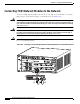

Table Of Contents
20-2
Cisco Network Modules Hardware Installation Guide
OL-2485-20
Chapter 20 Connecting T3/E3 Network Modules
Connecting T3/E3 Network Modules to the Network
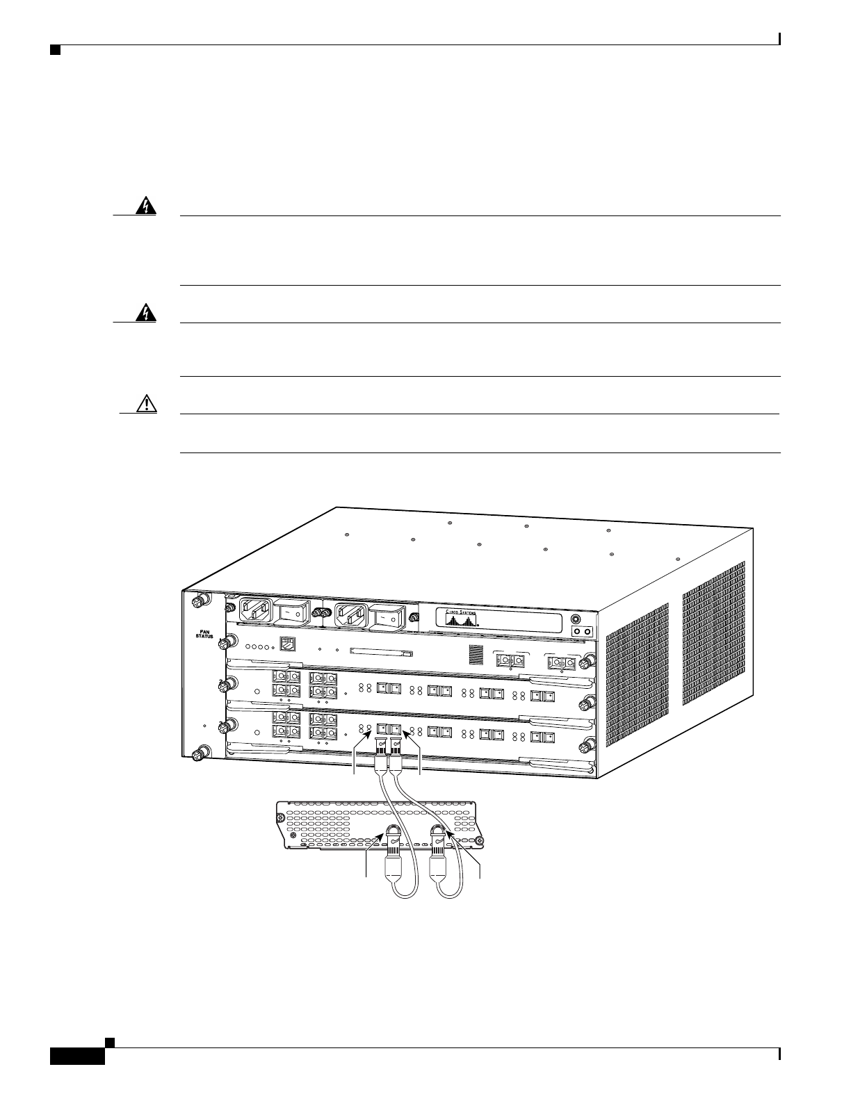
Connecting T3/E3 Network Modules to the Network
To connect a T3/E3 network module to the network, use a 75-ohm 728-A coaxial cable to connect the
BNC connector on the network module to a networking device. (See Figure 20-2.)
Warning
This equipment contains a ring signal generator (ringer), which is a source of hazardous voltage. Do
not touch the RJ-11 (phone) port wires (conductors), theconductorsofacableconnected to the RJ-11
port, or the associated circuit-boardwhenthe ringer is active. The ringerisactivatedby an incoming
call. Statement 1042
Warning
If the symbolof suitability with an overlaid cross appears above a port,you must not connectthe port
to a public network that follows the European Union standards. Connecting the port to this type of
public network can cause severe injury or damage your router. Statement 1031
Caution To minimize transient surges, the internal wiring should not be routed in the same conduit with power
lines or external telephone lines.
Figure 20-2 Connecting a T3/E3 Network Module to a Networking Device (Cisco 7603 Router Shown)
72715
SUPERVISOR2
WS-X6K-SUP2-2GE
STATUS
SYSTEM
CONSOLE
PWR MGMT
RESET
CONSOLE
CONSOLE
PORT
MODE
PCMCIA EJECT
PORT 1
PORT 2
Switch Load
100%
1%
LINK
LINK
OSM-4OC12 POS-SI
4 PORT OC-12 POS SM IR
STATUS
1
1
2
2
3
3
4
4
RESET
LINK
LINK
LINK
LINK
CARRIER
ALARM
CARRIER
ALARM
CARRIER
ALARM
CARRIER
ALARM
ACTIVE
TX
RX
TX
PORT 1
RX
ACTIVE
TX
RX
TX
PORT 2
RX
ACTIVE
TX
RX
TX
PORT 3
RX
ACTIVE
TX
RX
TX
PORT4
RX
OSM-4OC12 POS-SI
4 PORT OC-12 POS SM IR
STATUS
1
1
2
2
3
3
4
4
RESET
LINK
LINK
LINK
LINK
CARRIER
ALARM
CARRIER
ALARM
CARRIER
ALARM
CARRIER
ALARM
ACTIVE
TX
RX
TX
PORT 1
RX
ACTIVE
TX
RX
TX
PORT 2
RX
ACTIVE
TX
RX
TX
PORT 3
RX
ACTIVE
TX
RX
TX
PORT4
RX
SEE MANUAL BEFORE INSTALLING NETWORK MODULE
NM-1T3/E3
LP
AIS
AL
CD
TX
RX
FERF/RAI
T3/E3
EN
TX
RX
TX
RX