C H A P T E R 24 Configuring ATM Router Module Interfaces This chapter describes steps required to configure the ATM router module on the Catalyst 8540 MSR, Catalyst 8510 MSR, and LightStream 1010 ATM switch routers, and the enhanced ATM router module for the Catalyst 8540 MSR. The ATM router module allows you to integrate Layer 3 switching with ATM switching on the same ATM switch router.
Chapter 24 Configuring ATM Router Module Interfaces Overview of the ATM Router Module Overview of the ATM Router Module The ATM router module allows you to integrate Layer 3 routing and ATM switching within a single chassis. When you install the ATM router module, you no longer need to choose either Layer 3 or ATM technology, as is frequently the case with enterprise, campus, and MAN applications. The ATM router module can perform one or more of the functions described in Figure 24-1.
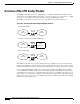
Chapter 24 Configuring ATM Router Module Interfaces Overview of the ATM Router Module Figure 24-2 ATM Router Module Traffic Flow (Catalyst 8540 MSR) ATM cells NNI LANE signalling Interface slot ATM interface module IPX packets/ Ethernet frames FE or GE interface module Interface slot Route processor Switch processor Switch processor Switch processor Route processor Interface slot Interface slot Interface slot ATM router module Interface slot Power supply 2 31333 Power supply 1 Catalyst 8540 MSR Enhan
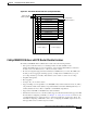
Chapter 24 Configuring ATM Router Module Interfaces Overview of the ATM Router Module Note • IP fragmentation support. • IP 6-path load balancing support. • Supports OAM-based PVC management. • Supports Bridge Group Virtual Interface (BVI). • Supports integrated routing and bridging (IRB). The Catalyst 8540 MSR enhanced ATM router module does not support LANE clients. The ATM router module has no external interfaces.
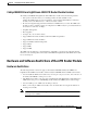
Chapter 24 Configuring ATM Router Module Interfaces Hardware and Software Restrictions of the ATM Router Module Catalyst 8510 MSR and LightStream 1010 ATM Router Module Features The Catalyst 8510 MSR and LightStream 1010 ATM router module offers the following benefits: • Interoperates with all of the Layer 3 switching interface modules available for the Catalyst 8510 CSR chassis.
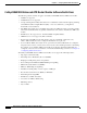
Chapter 24 Configuring ATM Router Module Interfaces Hardware and Software Restrictions of the ATM Router Module Catalyst 8540 MSR Enhanced ATM Router Module Software Restrictions The following software restrictions apply to the Catalyst 8540 MSR enhanced ATM router module: • LANE is not supported. • LANE Clients are not supported. • Use tag switching functionality with caution. Do not distribute routes learned through tag switching to Fast Ethernet (FE) or Gigabit Ethernet (GE), or vice versa.
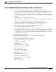
Chapter 24 Configuring ATM Router Module Interfaces Hardware and Software Restrictions of the ATM Router Module Catalyst 8540 MSR ATM Router Module Software Restrictions The following software restrictions apply to the Catalyst 8540 MSR ATM router module: • Use tag switching functionality with caution. Do not distribute routes learned through tag switching to FE or GE, or vice versa. Otherwise, you might have unreachable route destinations.
Chapter 24 Configuring ATM Router Module Interfaces Hardware and Software Restrictions of the ATM Router Module Catalyst 8540 MSR and LightStream 1010 ATM Router Module Software Restrictions The following software restrictions apply to the Catalyst 8540 MSR enhanced ATM router module: • Use tag switching functionality with caution. Do not distribute routes learned through tag switching to FE or GE, or vice versa. Otherwise, you might have unreachable route destinations.
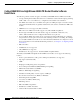
Chapter 24 Configuring ATM Router Module Interfaces Configuring ATM Router Module Interfaces • IP fragmentation. • IP 6-path load balancing. Note The ATM router module is only supported on ATM switches which have a multiservice ATM switch processor installed. Note The LightStream 1010 system software image does not include support for the ATM router module or Layer 3 features. You can download this image to a LightStream 1010 ATM switch router with a multiservice ATM switch processor installed.
Chapter 24 Configuring ATM Router Module Interfaces Configuring ATM Router Module Interfaces Default ATM Router Module Interface Configuration Without Autoconfiguration If ILMI is disabled or if the connecting end node does not support ILMI, the following defaults are assigned to all ATM router module interfaces: Note • ATM interface type = UNI • UNI version = 3.
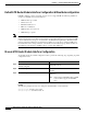
Chapter 24 Configuring ATM Router Module Interfaces Configuring LECs on ATM Router Module Interfaces (Catalyst 8540 MSR) Configuring LECs on ATM Router Module Interfaces (Catalyst 8540 MSR) The procedures for configuring LANE clients (LECs) on the ATM router module are the same as for the configuration of LECs on the route processor, with one exception: To specify an ATM router module interface, rather than the route processor interface, use the interface atm card/subcard/port command.
Chapter 24 Configuring ATM Router Module Interfaces Configuring LECs on ATM Router Module Interfaces (Catalyst 8540 MSR) Example The following example shows how to configure two LECs on an ATM router module interface: Switch# configure terminal Switch(config)# interface atm 1/0/0.4 multipoint Switch(config-subif)# ip address 40.0.0.1 255.0.0.0 Switch(config-subif)# lane client ethernet VLAN4 Switch(config-subif)# exit Switch(config)# interface atm 1/0/0.5 multipoint Switch(config-subif)# ip address 50.
Chapter 24 Configuring ATM Router Module Interfaces Configuring LECs on ATM Router Module Interfaces (Catalyst 8540 MSR) Router 1 ATM Interface Router1# configure terminal Router1(config)# interface atm 2/0 Router1(config-if)# ip address 1.0.0.1 255.0.0.
Chapter 24 Configuring ATM Router Module Interfaces Configuring LECs on ATM Router Module Interfaces (Catalyst 8540 MSR) Router 1 ATM Interface Router1# configure terminal Router1(config)# interface atm 2/0 Router1(config-if)# ip address 1.0.0.1 255.0.0.
Chapter 24 Configuring ATM Router Module Interfaces Configuring LECs on ATM Router Module Interfaces (Catalyst 8540 MSR) LANE Bridging Between ATM and Ethernet The following example show how to configure LANE bridging between ATM and Ethernet using the ATM router module. Figure 24-5 shows an example of a network for LANE bridging between ATM and Ethernet.
Chapter 24 Configuring ATM Router Module Interfaces Configuring Multiprotocol Encapsulation over ATM Router 2 Ethernet Interface Router2# configure terminal Router2(config)# interface ethernet 9/0/0 Router2(config-if)# bridge-group 1 Router2(config-if)# end Router2# Router 2 Bridge Interface Router2# configure terminal Router2(config)# interface BVI1 Router2(config-if)# ip address 130.2.3.4 255.255.255.
Chapter 24 Configuring ATM Router Module Interfaces Configuring Multiprotocol Encapsulation over ATM Note Traffic shaping and policing are not supported on the ATM router module interfaces; for traffic shaping and policing on ATM connections, use VP tunnels. For more information on VP tunnels, see Chapter 6, “Configuring Virtual Connections.
Chapter 24 Configuring ATM Router Module Interfaces Configuring Multiprotocol Encapsulation over ATM Multiprotocol Encapsulation over ATM Configuration Example The following example shows how to configure for multiprotocol encapsulation over ATM with two routers and a ATM switch router. The ATM switch router has an ATM router module in slot 0, a Fast Ethernet interface module in slot 1, and an ATM interface module in slot 3. One router has an ATM interface processor in slot 3.
Chapter 24 Configuring ATM Router Module Interfaces Configuring Classical IP over ATM in a PVC Environment Ethernet Router RouterB# configure terminal RouterB(config)# ipx routing RouterB(config)# interface fastethernet 2/0 RouterB(config-if)# ip address 20.1.1.1 255.255.255.
Chapter 24 Configuring ATM Router Module Interfaces Configuring Classical IP over ATM in an SVC Environment For a detailed description of the role and operation of the ATM ARP server, refer to the Guide to ATM Technology. The ATM switch router can be configured as an ATM ARP client, thereby being able to work with any ATM ARP server conforming to RFC 1577. Alternatively, one of the ATM switch routers in a logical IP subnet (LIS) can be configured to act as the ATM ARP server itself.
Chapter 24 Configuring ATM Router Module Interfaces Configuring Classical IP over ATM in an SVC Environment NSAP Address Example Figure 24-7 shows three ATM switch routers and a router connected using classical IP over ATM. Figure 24-7 Classical IP over ATM Connection Setup Switch client B 123.233.45.3 Router client C 123.233.45.6 Switch ARP server 123.233.45.2 Switch client A 123.233.45.1 27082 ATM network 123.233.45.
Chapter 24 Configuring ATM Router Module Interfaces Configuring Classical IP over ATM in an SVC Environment Configuring as an ATM ARP Server Cisco’s implementation of the ATM ARP server supports a single, nonredundant server per LIS, and one ATM ARP server per subinterface. Thus, a single ATM switch router can support multiple ARP servers by using multiple interfaces.
Chapter 24 Configuring ATM Router Module Interfaces Configuring Classical IP over ATM in an SVC Environment Displaying the IP-over-ATM Interface Configuration To show the IP-over-ATM interface configuration, use the following EXEC commands: Command Purpose show atm arp-server Shows the ATM interface ARP configuration. show atm map Shows the ATM map list configuration.
Chapter 24 Configuring ATM Router Module Interfaces Configuring Bridging Configuring Bridging All PVCs configured on ATM router module interfaces are used for bridging. To configure bridging on an ATM router module interface, use the following commands, beginning in global configuration mode: Command Purpose Step 1 Switch(config)# interface atm card/subcard/port Specifies the interface on the ATM router module to configure.
Chapter 24 Configuring ATM Router Module Interfaces Configuring Bridging Switch(config)# interface atm 3/0/0 Switch(config-if)# atm pvc 2 200 interface atm 1/0/0 0 200 Switch(config-if)# bridge-group 5 Switch(config-if)# end Switch(config)# interface fastethernet 0/0/0 Switch(config-if)# no cdp enable Switch(config-if)# bridge-group 5 Switch(config-if)# end Switch(config)# bridge 5 protocol ieee Configuring Packet Flooding on a PVC Typically, a specific static map list configuration is not required for b
Chapter 24 Configuring ATM Router Module Interfaces Configuring Bridging Example In the following example only PVC 2, 200 is used for packet flooding: Switch(config)# interface atm 3/0/0 Switch(config-if)# no ip address Switch(config-if)# no ip directed-broadcast Switch(config-if)# map-group bg_1 Switch(config-if)# atm pvc 2 200 interface atm 1/0/1 0 200 Switch(config-if)# atm pvc 2 201 interface atm 1/0/1 0 300 Switch(config-if)# bridge-group 5 Switch(config-if)# end Switch(config)# map-list bg_1 Switc
Chapter 24 Configuring ATM Router Module Interfaces Configuring IP Multicast Configuring IP Multicast To configure IP multicast over an RFC 1483 permanent virtual connection (PVC) on an ATM router module, use the following commands, beginning in global configuration mode: Command Purpose Step 1 Switch(config)# ip multicast-routing Enables IP multicast routing. Step 2 Switch(config)# interface atm card/subcard/port.
Chapter 24 Configuring ATM Router Module Interfaces About Rate Limiting Rate limiting can be applied to individual interfaces. When an interface is configured with this feature, the traffic rate will be monitored by the Ethernet processor interface microcode to verify conformity. Non-conforming traffic is dropped, conforming traffic passes through without any changes.
Chapter 24 Configuring ATM Router Module Interfaces About Rate Limiting Example The following is an example of how to configure rate limiting on your switch router: Router# configure terminal Enter configuration commands, one per line.
Chapter 24 Configuring ATM Router Module Interfaces About Rate Limiting ATM and Layer 3 Switch Router Software Configuration Guide 24-30 OL-1911-05