
Network Card User Manual
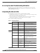
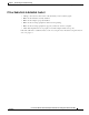
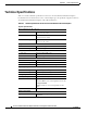
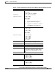
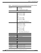
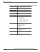

Table Of Contents
- Cisco Aironet Wireless LAN Client Adapters Installation and Configuration Guide for MS-DOS
- Contents
- Preface
- Audience
- Purpose
- Organization
- Conventions
- Related Publications
- Obtaining Documentation
- Obtaining Technical Assistance
- Introduction to the Wireless LAN Adapters
- Parts of the Client Adapter
- Radio Ranges
- Data Transparency and Protocols
- System Configurations
- Coverage Options
- Safety Information
- Unpacking the Client Adapter
- Inserting the Client Adapter into a Computing Device
- Removing the Client Adapter
- Driver Overview
- Windows for Workgroups 3.11 NDIS2 Installation
- DOS NDIS2 Installation
- ODI Driver Installation
- Additional Requirements and Features
- Driver Keywords and Settings
- Site Survey and Link Test
- Loading New Firmware Versions
- DOS Utilities
- Accessing the Latest Troubleshooting Information
- Interpreting the Indicator LEDs
- Technical Specifications
- Channel Sets
- Maximum Power Levels and Antenna Gains
- Manufacturers Federal Communication Commission Declaration of Conformity Statement
- Department of Communications – Canada
- European Community, Switzerland, Norway, Iceland, and Liechtenstein
- Declaration of Conformity for RF Exposure
- Guidelines for Operating Cisco Aironet Wireless LAN Client Adapters in Japan
- Explosive Device Proximity Warning
- Lightning Activity Warning
- Installation Warning
- Circuit Breaker (15A) Warning

5-2
Cisco Aironet Wireless LAN Client Adapters Installation and Configuration Guide for MS-DOS
OL-1744-02
Chapter5 Error Messages and Trouble Shooting
Accessing the Latest Troubleshooting Information
Accessing the Latest Troubleshooting Information
This chapter provides basic troubleshooting tips for your client adapter. For more up-to-date and
complex troubleshooting information, refer to the TAC web site at http://www.cisco.com/tac. Select
Wireless Technologies under Top Issues.
Interpreting the Indicator LEDs
The client adapter shows messages and error conditions through its two LEDs:
• Link Integrity/Power LED (green)— This LED is on when the client adapter is receiving power and
blinks slowly when the adapter is linked with the network.
• Link Activity LED (amber)—This LED blinks quickly when the client adapter is receiving or
transmitting data and blinks in a repeating pattern to show an error condition.
Table 5-1 interprets the LED operating messages.
Table 5-1 LED Operating Messages
Green LED Amber LED Condition
Normal
Operation
Blinking quickly Blinking quickly Power is on, self-test is OK, and client
adapter is scanning for a network.
Blinking slowly Blinking quickly Client adapter is associated to an access
point.
Continuously on or
blinking slowly
Blinking Client adapter is transmitting or receiving
data while associated to an access point.
Off Blinking quickly Client adapter is in power save mode.
On continuously Blinking quickly Client adapter is in ad hoc mode.
Error
Conditions
Off Off Client adapter is not receiving power, or an
error has occurred.
Off 1 blink at 2-second
rate
RAM failure. Refer to the “Obtaining
Technical Assistance” section in the Preface
for technical support information.
Off 2 fast blinks,
2-second pause
Flash boot block checksum failure. Refer to
the “Obtaining Technical Assistance” section
in the Preface for technical support
information.
Off 3 fast blinks,
2-second pause
Firmware checksum failure. Reload the
firmware.
Off 4 fast blinks,
2-second pause
MAC address error (error reading MAC
chip). Reload the firmware.
Off 5 fast blinks,
2-second pause
PHY access error. Refer to the “Obtaining
Technical Assistance” section in the Preface
for technical support information.
Off 6 fast blinks,
2-second pause
Incompatible firmware. Load the correct
firmware version.