
Network Card User Manual
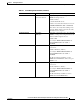
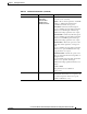
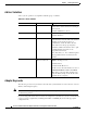
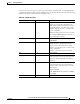

Table Of Contents
- Cisco Aironet Wireless LAN Client Adapters Installation and Configuration Guide for MS-DOS
- Contents
- Preface
- Audience
- Purpose
- Organization
- Conventions
- Related Publications
- Obtaining Documentation
- Obtaining Technical Assistance
- Introduction to the Wireless LAN Adapters
- Parts of the Client Adapter
- Radio Ranges
- Data Transparency and Protocols
- System Configurations
- Coverage Options
- Safety Information
- Unpacking the Client Adapter
- Inserting the Client Adapter into a Computing Device
- Removing the Client Adapter
- Driver Overview
- Windows for Workgroups 3.11 NDIS2 Installation
- DOS NDIS2 Installation
- ODI Driver Installation
- Additional Requirements and Features
- Driver Keywords and Settings
- Site Survey and Link Test
- Loading New Firmware Versions
- DOS Utilities
- Accessing the Latest Troubleshooting Information
- Interpreting the Indicator LEDs
- Technical Specifications
- Channel Sets
- Maximum Power Levels and Antenna Gains
- Manufacturers Federal Communication Commission Declaration of Conformity Statement
- Department of Communications – Canada
- European Community, Switzerland, Norway, Iceland, and Liechtenstein
- Declaration of Conformity for RF Exposure
- Guidelines for Operating Cisco Aironet Wireless LAN Client Adapters in Japan
- Explosive Device Proximity Warning
- Lightning Activity Warning
- Installation Warning
- Circuit Breaker (15A) Warning

3-17
Cisco Aironet Wireless LAN Client Adapters Installation and Configuration Guide for MS-DOS
OL-1744-02
Chapter 3 Installing the Software
Driver Keywords and Settings
If you are not using card services, your host system must have an Intel 82365 or compatible PC Card
controller chip. The driver then configures the PC Card controller chip directly, and each of the following
parameters should be specified in your configuration file.
Table 3-11 Adapter Keywords
Keyword Value Description
PORTBASE 0–0xFFFF (Optional)—Specifies the starting address for
a block of 32 consecutive 16-bit I/O ports.
Make sure the block of I/O addresses does not
overlap the address of another device in the
machine. This can be used to override a card
service assignment.
Default: 0x140 (if card services are not used)
The starting PORTBASE address must be on
an even 0x40 byte boundary.
PORT 0–0xFFFF Only valid in NET.CFG file (same as
PORTBASE).
INT 2–15 (Optional)— Specifies the hardware interrupt
the PC Card uses. The Interrupt must be
unique (not used by another device in the
machine). Use this keyword to override a card
service assignment.
Default: 11 (if card services are not used)
IRQ 2–15 Same as INT.
SOCKET 0–7 (Optional)— Ignored if card services are
used. If card services are not used, this is the
PC Card socket the PC Card is inserted in.
Default: 0
MEMORY 0xC000–0xDF00 (Optional)—Ignored if If card services are
used. If card services are not used, this is a
block of memory the driver uses to view the
PC Card CIS.
Default: 0xD000
In the NET.CFG file, the parameter is D0000,
not 0xD000.
MEM 0xC00–0xDF00 Same as MEMORY.