
Network Card User Manual
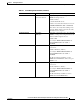
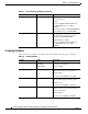
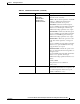
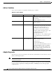
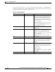

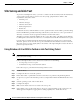
Table Of Contents
- Cisco Aironet Wireless LAN Client Adapters Installation and Configuration Guide for MS-DOS
- Contents
- Preface
- Audience
- Purpose
- Organization
- Conventions
- Related Publications
- Obtaining Documentation
- Obtaining Technical Assistance
- Introduction to the Wireless LAN Adapters
- Parts of the Client Adapter
- Radio Ranges
- Data Transparency and Protocols
- System Configurations
- Coverage Options
- Safety Information
- Unpacking the Client Adapter
- Inserting the Client Adapter into a Computing Device
- Removing the Client Adapter
- Driver Overview
- Windows for Workgroups 3.11 NDIS2 Installation
- DOS NDIS2 Installation
- ODI Driver Installation
- Additional Requirements and Features
- Driver Keywords and Settings
- Site Survey and Link Test
- Loading New Firmware Versions
- DOS Utilities
- Accessing the Latest Troubleshooting Information
- Interpreting the Indicator LEDs
- Technical Specifications
- Channel Sets
- Maximum Power Levels and Antenna Gains
- Manufacturers Federal Communication Commission Declaration of Conformity Statement
- Department of Communications – Canada
- European Community, Switzerland, Norway, Iceland, and Liechtenstein
- Declaration of Conformity for RF Exposure
- Guidelines for Operating Cisco Aironet Wireless LAN Client Adapters in Japan
- Explosive Device Proximity Warning
- Lightning Activity Warning
- Installation Warning
- Circuit Breaker (15A) Warning

3-16
Cisco Aironet Wireless LAN Client Adapters Installation and Configuration Guide for MS-DOS
OL-1744-02
Chapter 3 Installing the Software
Driver Keywords and Settings
Ad Hoc Variables
Ad hoc system operation is accomplished with this group of variables.
Adapter Keywords
The following is a list of keywords that control the host system hardware resources the Cisco Aironet
Wireless LAN Adapter requires.
Note At a minimum, the adapter requires 64 consecutive 16-bit I/O ports, one nonsharable Interrupt and
one PC Card type II slot.
If you are using card services, these resources are assigned for you. However, you can override the card
services resource assignments by including the PortBase or INT/IRQ keywords in the appropriate
configuration file.
Table 3-10 Ad Hoc Variables
Variable Value Description
JOINNETTO 0–0xFFFF (Optional)—Determines the amount of time
that an ad hoc station scans before starting its
own network.
Default: 10,000 Kusec (10 sec)
BEACONPERIOD 0–0xFFFF (Optional)—Specifies the beaconing interval.
Default: 100 Kusec
DSCHANNEL 0–14 (Optional)—This variable is valid only for a
node that starts a network. This is the channel
identifier specifying the frequency to
communicate on. For all other nodes, the
radio will scan for the proper frequency.
Default: 0 (which will cause the radio to pick
a default channel appropriate for its
programmed carrier set)
Any other value (1 to 14) is validated against
the programmed carrier set and rejected if
invalid.
ATIMDURATION Between 0 and less than
the beacon interval
(Optional)—Specifies the length of time for
ATIMs following a beacon.
Default: 5 Kusec
Constant Awake Mode is 0.
In ad hoc mode, this value must be non-zero if
POWERSAVEMODE is PSP or FASTPSP.
This value is only used when starting a new
network. When joining a network, the value
currently in use is adopted.