
Network Card User Manual
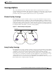
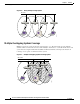
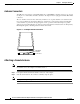
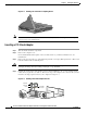
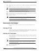
Table Of Contents
- Cisco Aironet Wireless LAN Client Adapters Installation and Configuration Guide for MS-DOS
- Contents
- Preface
- Audience
- Purpose
- Organization
- Conventions
- Related Publications
- Obtaining Documentation
- Obtaining Technical Assistance
- Introduction to the Wireless LAN Adapters
- Parts of the Client Adapter
- Radio Ranges
- Data Transparency and Protocols
- System Configurations
- Coverage Options
- Safety Information
- Unpacking the Client Adapter
- Inserting the Client Adapter into a Computing Device
- Removing the Client Adapter
- Driver Overview
- Windows for Workgroups 3.11 NDIS2 Installation
- DOS NDIS2 Installation
- ODI Driver Installation
- Additional Requirements and Features
- Driver Keywords and Settings
- Site Survey and Link Test
- Loading New Firmware Versions
- DOS Utilities
- Accessing the Latest Troubleshooting Information
- Interpreting the Indicator LEDs
- Technical Specifications
- Channel Sets
- Maximum Power Levels and Antenna Gains
- Manufacturers Federal Communication Commission Declaration of Conformity Statement
- Department of Communications – Canada
- European Community, Switzerland, Norway, Iceland, and Liechtenstein
- Declaration of Conformity for RF Exposure
- Guidelines for Operating Cisco Aironet Wireless LAN Client Adapters in Japan
- Explosive Device Proximity Warning
- Lightning Activity Warning
- Installation Warning
- Circuit Breaker (15A) Warning
2-6
Cisco Aironet Wireless LAN Client Adapters Installation and Configuration Guide for MS-DOS
OL-1744-02
Chapter 2 Installing the Hardware
Inserting the Client Adapter into a Computing Device
Figure 2-2 Inserting a PC Card into a Computing Device
Note You can remove and reinsert your PC card when necessary. See the “Removing the Client Adapter”
section on page 2-7 for instructions.
Inserting a PCI Client Adapter
Step 1 Turn off the PC and all its components.
Step 2 Remove the computer cover.
On most Pentium PCs, PCI expansion slots are white. Refer to your PC documentation for slot
identification.
Step 3 Remove the screw from the top of the CPU back panel above an empty PCI expansion slot. This screw
holds the metal bracket on the back panel.
Caution Static electricity can damage your client adapter. Before removing the adapter from the antistatic
packaging, discharge static by touching a metal part of a grounded PC.
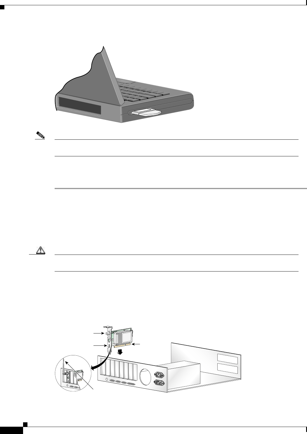
Step 4 Examine the client adapter. The antenna connector and the LEDs face out of your computer and are
visible when you put the cover back on. The bottom edge of the adapter is the connector that you will
insert into an empty expansion slot in your computer. See Figure 2-3.
Figure 2-3 Inserting a PCI Client Adapter into a PC
Antenna
connector
LEDs
Card edge
connector
Standard 2 dBi
dipole antenna
47521