
Network Card User Manual
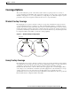
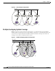
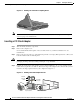
Table Of Contents
- Cisco Aironet Wireless LAN Client Adapters Installation and Configuration Guide for MS-DOS
- Contents
- Preface
- Audience
- Purpose
- Organization
- Conventions
- Related Publications
- Obtaining Documentation
- Obtaining Technical Assistance
- Introduction to the Wireless LAN Adapters
- Parts of the Client Adapter
- Radio Ranges
- Data Transparency and Protocols
- System Configurations
- Coverage Options
- Safety Information
- Unpacking the Client Adapter
- Inserting the Client Adapter into a Computing Device
- Removing the Client Adapter
- Driver Overview
- Windows for Workgroups 3.11 NDIS2 Installation
- DOS NDIS2 Installation
- ODI Driver Installation
- Additional Requirements and Features
- Driver Keywords and Settings
- Site Survey and Link Test
- Loading New Firmware Versions
- DOS Utilities
- Accessing the Latest Troubleshooting Information
- Interpreting the Indicator LEDs
- Technical Specifications
- Channel Sets
- Maximum Power Levels and Antenna Gains
- Manufacturers Federal Communication Commission Declaration of Conformity Statement
- Department of Communications – Canada
- European Community, Switzerland, Norway, Iceland, and Liechtenstein
- Declaration of Conformity for RF Exposure
- Guidelines for Operating Cisco Aironet Wireless LAN Client Adapters in Japan
- Explosive Device Proximity Warning
- Lightning Activity Warning
- Installation Warning
- Circuit Breaker (15A) Warning

2-5
Cisco Aironet Wireless LAN Client Adapters Installation and Configuration Guide for MS-DOS
OL-1744-02
Chapter 2 Installing the Hardware
Inserting the Client Adapter into a Computing Device
Detaching a Remote Antenna
Step 1 Remove the adapter from the PC card slot.
Step 2 Grasp the end of the antenna cable lead by the connector.
Step 3 Gently pull the connector away from the adapter until it comes free.
Inserting the Client Adapter into a Computing Device
This section provides instructions for inserting a PC card or a PCI client adapter into a computing device.
Caution These procedures and the physical connections they describe apply generally to conventional PC card
slots and PCI expansion slots. In cases of custom or nonconventional equipment, be alert to possible
differences in PC card slot and PCI expansion slot configurations.
Inserting a PC Card
Step 1 Before you begin, examine the PC card. One end has a dual-row, 68-pin PC card connector. The card is
keyed so that it can be inserted only one way into the PC card slot.
Step 2 Turn on your computer, let the operating system boot up completely, and follow the remaining steps in
this section to insert the PC card.
Caution Do not force the PC card into your computer’s PC card slot. Forcing it will damage both the card and
the slot. If the PC card does not insert easily, remove the card and reinsert it.
Step 3 Hold the PC card with the Cisco logo facing up and insert it into the PC card slot, applying just enough
pressure to make sure it is fully seated. See Figure 2-2.