
Network Card User Manual
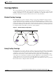
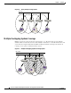
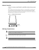
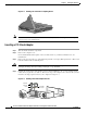
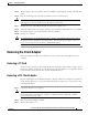
Table Of Contents
- Cisco Aironet Wireless LAN Client Adapters Installation and Configuration Guide for MS-DOS
- Contents
- Preface
- Audience
- Purpose
- Organization
- Conventions
- Related Publications
- Obtaining Documentation
- Obtaining Technical Assistance
- Introduction to the Wireless LAN Adapters
- Parts of the Client Adapter
- Radio Ranges
- Data Transparency and Protocols
- System Configurations
- Coverage Options
- Safety Information
- Unpacking the Client Adapter
- Inserting the Client Adapter into a Computing Device
- Removing the Client Adapter
- Driver Overview
- Windows for Workgroups 3.11 NDIS2 Installation
- DOS NDIS2 Installation
- ODI Driver Installation
- Additional Requirements and Features
- Driver Keywords and Settings
- Site Survey and Link Test
- Loading New Firmware Versions
- DOS Utilities
- Accessing the Latest Troubleshooting Information
- Interpreting the Indicator LEDs
- Technical Specifications
- Channel Sets
- Maximum Power Levels and Antenna Gains
- Manufacturers Federal Communication Commission Declaration of Conformity Statement
- Department of Communications – Canada
- European Community, Switzerland, Norway, Iceland, and Liechtenstein
- Declaration of Conformity for RF Exposure
- Guidelines for Operating Cisco Aironet Wireless LAN Client Adapters in Japan
- Explosive Device Proximity Warning
- Lightning Activity Warning
- Installation Warning
- Circuit Breaker (15A) Warning
2-4
Cisco Aironet Wireless LAN Client Adapters Installation and Configuration Guide for MS-DOS
OL-1744-02
Chapter 2 Installing the Hardware
Unpacking the Client Adapter
Antenna Connectors
The LM card version has two female MicroMate (also called MMCX ) antenna connectors on one end.
See Figure 2-1. All antennas and cables attached to the adapter must be equipped with male MicroMate
connectors.
The two antenna connectors allow a Diversity Antenna or two separate antennas to be attached to the
Cisco Aironet Wireless LAN Adapter. When two antennas are connected, the adapter automatically
selects antennas to provide the strongest signal for radio operations. This feature improves packet
delivery and system throughput by avoiding reception and transmission instances that are hampered by
RF multipath signals or blocking structures in the environment.
Figure 2-1 LM Adapter Antenna Connections
Attaching a Remote Antenna
Note The PCM version of the adapter comes with the antenna installed. If you need to remove or change
the antenna, remove the adapter from the PC card slot.
Step 1 Line up the antenna cable leads with the connectors on the adapter.
Step 2 Slide the cable leads into the connectors until they snap into place.
Note The J1 port is the primary port. If the antenna has only 1 MMCX connector, attach it to the J1 port.
MicroMate
Antenna
Connectors
J1 J2