
Network Card User Manual

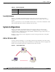
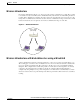
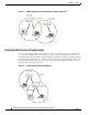
Table Of Contents
- Cisco Aironet Wireless LAN Client Adapters Installation and Configuration Guide for MS-DOS
- Contents
- Preface
- Audience
- Purpose
- Organization
- Conventions
- Related Publications
- Obtaining Documentation
- Obtaining Technical Assistance
- Introduction to the Wireless LAN Adapters
- Parts of the Client Adapter
- Radio Ranges
- Data Transparency and Protocols
- System Configurations
- Coverage Options
- Safety Information
- Unpacking the Client Adapter
- Inserting the Client Adapter into a Computing Device
- Removing the Client Adapter
- Driver Overview
- Windows for Workgroups 3.11 NDIS2 Installation
- DOS NDIS2 Installation
- ODI Driver Installation
- Additional Requirements and Features
- Driver Keywords and Settings
- Site Survey and Link Test
- Loading New Firmware Versions
- DOS Utilities
- Accessing the Latest Troubleshooting Information
- Interpreting the Indicator LEDs
- Technical Specifications
- Channel Sets
- Maximum Power Levels and Antenna Gains
- Manufacturers Federal Communication Commission Declaration of Conformity Statement
- Department of Communications – Canada
- European Community, Switzerland, Norway, Iceland, and Liechtenstein
- Declaration of Conformity for RF Exposure
- Guidelines for Operating Cisco Aironet Wireless LAN Client Adapters in Japan
- Explosive Device Proximity Warning
- Lightning Activity Warning
- Installation Warning
- Circuit Breaker (15A) Warning

1-4
Cisco Aironet Wireless LAN Adapters Installation and Configuration Guide for MS-DOS
OL-1744-02
Chapter1 Overview
Radio Ranges
Radio Antenna
The type of antenna used depends on your client adapter:
• PC cards have an integrated, permanently attached diversity antenna. The benefit of the diversity
antenna system is improved coverage. The system works by allowing the card to switch and sample
between its two antenna ports in order to select the optimum port for receiving data packets. As a
result, the card has a better chance of maintaining the radio frequency (RF) connection in areas of
interference. The antenna is located within the section of the card that protrudes from the PC card
slot when the card is installed.
• LM cards are shipped without an antenna; however, an antenna can be connected through the card’s
external connector. If a snap-on antenna is used, it should be operated in diversity mode. Otherwise,
the antenna mode used should correspond to the antenna port to which the antenna is connected.
• PCI client adapters are shipped with a 2-dBi dipole antenna that attaches to the adapter’s antenna
connector. However, other types of antennas can be used. PCI adapters can be operated only through
the antenna port located on the right side of the radio module (not to be confused with the antenna
connector on the card carrier).
Note External antennas used in combination with a power setting resulting in a radiated power level above
100 mW equivalent isotropic radiated power (EIRP) are not allowed for use within the European
community and other countries that have adopted the European R&TTE directive. CEPT
recommendation Rec 70.03, or both. For more details on legal combinations of power levels and
antennas in those countries, contact Cisco Corporate Compliance.
LEDs
The adapter has two LEDs that glow or blink to show the status of the adapter or to convey error
messages. See “Interpreting the Indicator LEDs” section on page 5-2 for an interpretation of the LED
codes.
Radio Ranges
Because of differences in component configuration, placement, and physical environment, every
network application is a unique installation. Before installing the system, you should perform a site
survey in order to determine the optimum utilization of networking components and to maximize range,
coverage, and network performance.
Here are some operating and environmental conditions that you need to consider:
• Data Rates—Sensitivity and range are inversely proportional to data bit rates. The maximum radio
range is achieved at the lowest workable data rate. There is a decrease in receiver threshold
sensitivity as the radio data rate increases.
• Antenna Type and Placement—Proper antenna configuration is a critical factor in maximizing radio
range. As a general guide, range increases in proportion to antenna height.