C H A P T E R 2 Using the NetFlow Collector User Interface Cisco NetFlow Collector (NFC), Release 6.0 has a web-based user interface (UI) for configuration, control, and reporting. Each collector instance has a web server that the user can start to enable the web-based UI.
Chapter 2 Using the NetFlow Collector User Interface Customizing the Cisco NetFlow Collector Interface Note The web-based UI only works with the collector located on the same machine. To access a different instance of Cisco NetFlow Collector you must start that collector’s web server and access it through the corresponding URL. Customizing the Cisco NetFlow Collector Interface The NFC application includes the tool /opt/CSCOnfc/bin/webconfig.
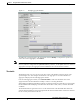
Chapter 2 Using the NetFlow Collector User Interface Using the Cisco NetFlow Collector User Interface Step 8 When the web configuration is complete, the following is displayed: NFC web configuration has been updated. Table 2-1 describes additional settings that can be customized for the Cisco NetFlow Collector web-based UI. Table 2-1 Setting Cisco NetFlow Collector User Interface Settings Description Default Value intfc- password Digest password for the password CNS/XML interface.
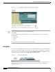
Chapter 2 Using the NetFlow Collector User Interface Using the Cisco NetFlow Collector User Interface Figure 2-1 Cisco NetFlow Collector User Interface Login Window To log in to Cisco NetFlow Collector, do the following: Step 1 From the Login window, enter your User ID and Password. Step 2 Click Login. The Cisco NetFlow Collector Main window appears.
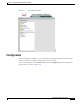
Chapter 2 Using the NetFlow Collector User Interface Configuration Figure 2-3 NFC UI Navigation Tree Configuration From the Configuration window you can perform tasks including specify global parameters; define fields, key builders, value builders and aggregators; and create filters. From the Cisco NetFlow Collector Main window, click the Configuration tab. The Configuration window appears, as shown in Figure 2-4.
Chapter 2 Using the NetFlow Collector User Interface Configuration Figure 2-4 NFC Configuration Window From this window you can access or configure the following: • Aggregators, page 2-7 • Fields, page 2-10 • Key Builders, page 2-11 • Value Builders, page 2-21 • Aggregation Schemes, page 2-25 • Filters, page 2-26 • NetFlow Export Source Groups, page 2-27 • NetFlow Export Source Access List, page 2-28 • BGP Peer, page 2-29 • Global, page 2-30 • Advanced, page 2-30 Cisco NetFlow Col
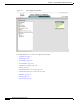
Chapter 2 Using the NetFlow Collector User Interface Configuration Aggregators Aggregators define how the Cisco NetFlow Collector receives NetFlow data, aggregates or combines the data, and generates output files. Click on the Aggregators folder of the NFC UI navigation tree to display a table of all existing aggregators, as shown in Figure 2-5.
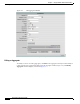
Chapter 2 Using the NetFlow Collector User Interface Configuration Figure 2-6 Add Aggregator Window Fill in the fields and click Submit to complete the operation. Editing an Aggregator To modify or remove an existing aggregator, click Edit for the aggregator which you wish to modify or remove from the list of aggregators displayed in the Aggregator window (Figure 2-6). The Modify Aggregator window displays, as shown in Figure 2-7.
Chapter 2 Using the NetFlow Collector User Interface Configuration Figure 2-7 Modify Aggregator Window To modify the selected aggregator, fill in the fields and click Modify to complete the operation. To remove the selected aggregator, click Remove. Note When a key or value builder, filter, or aggregation scheme is modified through the web-based user interface, collector configuration is updated immediately.
Chapter 2 Using the NetFlow Collector User Interface Configuration The top item in the tree is the name of the threshold. Directly beneath this is a top-level threshold condition or expression. Add the top-level threshold condition or expression by selecting Add condition or Add expression when the top item is selected. If the top-level threshold condition or expression evaluates to true when the threshold is evaluated, a threshold-crossing log is created.
Chapter 2 Using the NetFlow Collector User Interface Configuration Figure 2-8 Fields Window The NetFlow Export Field window, Figure 2-9, is displayed when adding or modifying a field. Fill in the form and click Add or Modify to complete the operation. From the Modify window you can also remove the currently displayed field. Click Add Alias or Remove Alias to add or remove an alias (alternate name) for this field. See the “Fields” section on page 4-4 for additional information about field definitions.
Chapter 2 Using the NetFlow Collector User Interface Configuration Figure 2-10 Key Builders Window All key builders have a unique ID and a type. The ID is displayed in the navigation tree and the key builder table. The attributes shown in the form depend on the type that is selected; different key builder types have different attributes.
Chapter 2 Using the NetFlow Collector User Interface Configuration BGP Attribute A BGP Attribute key builder looks up a BGP attribute from the Cisco NetFlow Collector BGP peer using an address from a flow. The complete AS path is a special case that uses both a source and a destination address from a flow. The BGP Attribute key builder has the following attributes. Attribute Description Output name Column name in output; defaults to the field ID if not specified.
Chapter 2 Using the NetFlow Collector User Interface Configuration Bit Field The Bit Field key builder obtains a subset of bits from a field in a flow. It has the following attributes. Attribute Description Output name Column name in output; defaults to the field ID if not specified. Field ID of the field in a flow from which to extract bits. Least significant bit Least significant bit of interest (starts at 0). Number of bits Number of bits of interest. Format Decimal or hexadecimal.
Chapter 2 Using the NetFlow Collector User Interface Configuration Customer Name The Customer Name key builder resolves the customer name from the input interface field. It has the following attributes: Attribute Description Output name Column name in output. Field ID of the field to obtain from a flow. Allow null value If not selected, an error is logged if a flow does not contain the indicated field. The Customer Name key builder requires configuration in the config/vpn.conf file.
Chapter 2 Using the NetFlow Collector User Interface Configuration Ingress CE The Ingress CE key builder resolves the ingress CE from the input interface field. It has the following attributes: Attribute Description Output name Column name in output. Field ID of the field to obtain from a flow. Allow null value If not selected, an error is logged if a flow does not contain the indicated field. This key builder requires configuration in the config/peList.conf file.
Chapter 2 Using the NetFlow Collector User Interface Configuration Integer Range Map An Integer Range Map key builder obtains an integer from a flow and maps the value to a string. It has the following attributes. Attribute Description Output name Column name in output; defaults to the field ID if not specified. Field ID of the field in a flow. Allow null value If not selected, an error is logged if a flow does not contain the indicated field. Default label Mapping result if no match is found.
Chapter 2 Using the NetFlow Collector User Interface Configuration IP Address Range Map An IP Address Range Map key builder obtains an IP address from a flow and maps the value to a string. It has the following attributes. Attribute Description Output name Column name in output; defaults to the field ID if not specified. Field ID of the field to look up from flows. Allow null value If set to false (default) and a flow does not contain field, an error is logged.
Chapter 2 Using the NetFlow Collector User Interface Configuration Multi-Field Map The Multi-Field Map editor is applet-based and is different than the forms for other key builder types because of the hierarchical nature of a multi-field map. A tree on the left-hand side of the Multi-Field Map editor shows the elements of the map. A form on the right-hand side of the Multi-Field Map editor shows the attributes for the selected item in the tree. The top level of the tree contains the following attributes.
Chapter 2 Using the NetFlow Collector User Interface Configuration Option Data An Option Data key builder obtains one or more key values from a flow and performs a look up using this result from an option data cache. The result of the mapping is the corresponding value from option data that was specified in the option data cache entry definition. The Option Data key builder has the following attributes. Attribute Description Output name Column name in output.
Chapter 2 Using the NetFlow Collector User Interface Configuration String A String key builder obtains a UTF-8 string value from a flow. It has the following attributes. Attribute Description Output name Column name in output. Field ID of the field to obtain from a flow. Regrex filter If specified, the regular expression is applied to the string in flow data. The first matching sequence becomes the value of the key. If the regrex contains one or more capturing groups, the first match is returned.
Chapter 2 Using the NetFlow Collector User Interface Configuration Figure 2-11 Value Builders Click on Add Value Builder to bring up an empty form for defining a new value builder. A value builder is created by specifying its type, associating it with a field (sometimes two or more fields such as for the Active Time type as shown in Figure 2-12), and specifying attributes specific to the selected type. Different forms are displayed depending on which value builder type is selected.
Chapter 2 Using the NetFlow Collector User Interface Configuration Active Time The Active Time value builder obtains a start time and an end time from fields in a flow and calculates the difference. It has the following attributes. Attribute Description Name Column name in output. Start time field ID of the start time field to obtain from a flow. End time field ID of the end time field to obtain from a flow. Usage Always leave set as Count.
Chapter 2 Using the NetFlow Collector User Interface Configuration Max Flow Byte Rate The Max Flow Byte Rate value builder determines the byte rate for each received flow and outputs the highest value found for all flows in an aggregation period. This builder was referred to as Max Burst Rate in previous releases. It has the following attributes. Attribute Description Name Column name in output. Start time field ID of the start time field to obtain from a flow.
Chapter 2 Using the NetFlow Collector User Interface Configuration Sum with Sampling Estimation The Sum with Sampling Estimation value builder obtains an integer value from a field in a flow, multiplies by the sampling rate in effect, and adds the estimate to a count. If not used with V9 export, the value is not scaled because the sampling rate is not known. It has the following attributes. Attribute Description Name Column name in output. Field ID of the integer field to obtain from a flow.
Chapter 2 Using the NetFlow Collector User Interface Configuration Figure 2-14 Note Modify Aggregation Scheme Removing an aggregation scheme that is in use by an aggregator can succeed but cause an invalid reference after the collector is restarted. Filters Filters provide a way to limit the amount and content of data that an aggregator processes. Clicking on the Filters folder of the navigation tree displays a table of all existing filters, as shown in Figure 2-15.
Chapter 2 Using the NetFlow Collector User Interface Configuration The Filter editor is applet-based. A tree on the left hand side of the filter editor shows the elements of the filter. A form on the right hand side of the filter editor contains the attributes for the currently selected item in the tree. The top item of the tree contains a unique identifier for the filter. Directly beneath the top of the tree is one filter condition or filter expression.
Chapter 2 Using the NetFlow Collector User Interface Configuration Click on the NetFlow Export Source Groups folder of the navigation tree to display a table of currently defined source groups, as shown in Figure 2-16. Click on the appropriate link to modify or remove a group. Click Add Group to bring up an empty form for defining a new source group. Figure 2-16 NetFlow Export Source Groups The NDE Source Group window, as shown in Figure 2-17, is shown when adding or modifying a source group.
Chapter 2 Using the NetFlow Collector User Interface Configuration Click on the appropriate link to add or remove a source device or group. Note that groups are obtained from the NetFlow Export Source Groups page. See the “Creating Access Lists” section on page 4-24 for additional information about configuring source access lists.
Chapter 2 Using the NetFlow Collector User Interface Configuration Figure 2-19 Local Peer Settings Window Global The settings in Figure 2-20 affect how the Cisco NetFlow Collector works in general. They are not specific to any aggregator, aggregation-scheme, or filter. Make any changes necessary and click Submit to store them. Some settings do not take affect until the Cisco NetFlow Collector is restarted.
Chapter 2 Using the NetFlow Collector User Interface Reports In limited cases where the configuration is more complex than the web-based UII supports, you will be directed to the Advanced window and the XML for the selected component will appear in the text area. Changes can then be made and submitted by clicking Submit XML. XML responses from the collector are displayed in Figure 2-21 in the text area after submitting a request.
Chapter 2 Using the NetFlow Collector User Interface Reports Figure 2-22 Reports Window From this window you can select the following: • Custom Reports, page 2-32 • Scheduled Reports, page 2-37 Custom Reports Custom reports are generated on demand from the NetFlow Collector output files on the collector machine. From the Custom Reports window, as shown in Figure 2-23, you can specify data that you want in the report and how you want it aggregated.
Chapter 2 Using the NetFlow Collector User Interface Reports Figure 2-23 Custom Reports Window The fields of the Custom Reports form are described in Table 2-2.
Chapter 2 Using the NetFlow Collector User Interface Reports Table 2-2 Custom Reports Fields Field Value Description Start Date A date string in the format of The data for the report will come from dd MMM yyyy where dd is the day of the Cisco NetFlow Collector output files that month, MMM is the abbreviated name of were generated on or after this date. the month, and yyyy is the four digit year. For example, 01Jan2074 for January 1st, 2007.
Chapter 2 Using the NetFlow Collector User Interface Reports Table 2-2 Custom Reports Fields (continued) Field Value Description Devices Combine devices, Separate devices, or Single device. For Single device the value should be the IP address of the device. Combine devices specifies that the report will aggregate data from different exporting devices into records based solely on the specified keys (See below). Each row of the report will contain a * for the value of the Device column.
Chapter 2 Using the NetFlow Collector User Interface Reports Table 2-2 Custom Reports Fields (continued) Field Value Description Report Type Top-N or Bottom-N Specifies if the report shows the Top-N or Bottom-N values as determined by the Ordered By value selection. N (Maximum Rows) A positive integer, N, no greater than 2147483647. Default value is 10. The maximum number of rows the report should contain for each exporting device.
Chapter 2 Using the NetFlow Collector User Interface Reports Figure 2-24 Report Templates List If you select Save as Template in a custom report form that was created from a template, you can modify the template definition if you keep the existing template name when prompted for the name. You can also create a new template by specifying a new name. For example, to create an hourly top-talkers report template for the previous hour, do the following: Step 1 Navigate Reports > Custom Reports.
Chapter 2 Using the NetFlow Collector User Interface Reports Figure 2-25 Scheduled Reports Window Clicking Add Scheduled Report brings up the Add Scheduled Report window to add a new scheduled report. Clicking Edit in any row in the list of scheduled reports displays the Modify Scheduled Report window to modify the selected scheduled report. Clicking Remove in any row deletes the selected schedule report.
Chapter 2 Using the NetFlow Collector User Interface Reports Figure 2-26 Add Scheduled Report Scheduled Report windows share many commonalities with the Custom Report window, but there are a few differences: • There is no Start Date, Start Time, End Date and End Time fields on Scheduled Report windows, because these values are pre-determined.
Chapter 2 Using the NetFlow Collector User Interface Reports Table 2-3 Scheduled Report Fields Field Value Description Scheduled Report ID String containing alphanumeric characters including a hyphen (-) and underscore (_). The ID to identify this type of report. Report Frequency Daily or Hourly. The default value is Daily. The frequency at which this type of report is run.
Chapter 2 Using the NetFlow Collector User Interface Reports Table 2-3 Scheduled Report Fields (continued) Field Value Description N (maximum Rows) A positive integer, N, no greater than 2147483647. Default value is 10. The maximum number of rows the report should contain for each exporting device. The total number of unique records in all the NetFlow Collector data files being reported can be much greater than the number of the records you might want to present in a report.
Chapter 2 Using the NetFlow Collector User Interface Reports Figure 2-27 Scheduled Reports Folder Reporting Features Cisco NetFlow Collector enables you to sort, graph, export, filter, and drill down on report data from the Report window, as shown in Figure 2-22.
Chapter 2 Using the NetFlow Collector User Interface Reports Sorting and Graphing Each column of a report supports ascending and descending sorting. Click on the column name to sort the table on that column. Value columns support creating a bar or pie graph of the values in that column. Click on the bar graph icon to generate a bar graph of that column’s values, as shown in Figure 2-28. Click on the pie graph icon to generate a pie graph of that column’s values, as shown in Figure 2-29.
Chapter 2 Using the NetFlow Collector User Interface Reports Figure 2-29 Sample Pie Graph Trending Trending reports can be launched from the Custom Report results window, as shown in Figure 2-30. This allows you to see how one or more report values vary over time for the report period. To launch the Trending report, select a result row then select the Trending button.
Chapter 2 Using the NetFlow Collector User Interface Status Export and Print The toolbar icons on the top right of the Report window allow you to export and print report data. Click on the export icon to export a report in CSV or PDF format. Click on the print icon to print the report or graph displayed in the current window. When exporting or printing reports, you can also select which rows to include. For example, the following dialog appears when the export icon is clicked, as shown in Figure 2-31.
Chapter 2 Using the NetFlow Collector User Interface Status Figure 2-32 Status Window From this window you can select the following: • Control, page 2-46 • Statistics, page 2-46 • Logs, page 2-49 Control Clicking on the Control node of the navigation tree displays the running status of the collector, as shown in Figure 2-33. If the collector is running, there will be a button to stop the collector. If the collector is not running, there will be a button to start the collector.
Chapter 2 Using the NetFlow Collector User Interface Status Figure 2-34 Health Monitor Statistics Window Clicking Refresh updates the statistics displayed in the window. Also, the form refreshes automatically every 30 seconds. The table contains the following fields; each statistic contains both the current and maximum value. Field Description CPU Utilization CPU utilization percentage reported by the operating system.
Chapter 2 Using the NetFlow Collector User Interface Status Clicking on Refresh updates the statistics shown. The table contains the following fields. Field Description Port/Protocol Port and protocol for these statistics. For example, 10001/udp. Packets Number of packets received. Received Number of flows received. Missed Number of flows missed (estimate based on sequence number). Out of sequence Number of out-of-sequence flows (estimate based on sequence number).
Chapter 2 Using the NetFlow Collector User Interface Status Logs The logs viewable from the web-based UI are listed under the Logs folder in the navigation tree. Clicking on a specific log loads that log file into the browser window, as shown in Figure 2-37.
Chapter 2 Using the NetFlow Collector User Interface Status Cisco NetFlow Collector User Guide 2-50 OL-11399-01