Cisco ICM Enterprise Edition SS7 Gateway Configuration Tool User Guide ICM Enterprise Edition Release 6.0(0) May 2004 Corporate Headquarters Cisco Systems, Inc. 170 West Tasman Drive San Jose, CA 95134-1706 USA http://www.cisco.
THE SPECIFICATIONS AND INFORMATION REGARDING THE PRODUCTS IN THIS MANUAL ARE SUBJECT TO CHANGE WITHOUT NOTICE. ALL STATEMENTS, INFORMATION, AND RECOMMENDATIONS IN THIS MANUAL ARE BELIEVED TO BE ACCURATE BUT ARE PRESENTED WITHOUT WARRANTY OF ANY KIND, EXPRESS OR IMPLIED. USERS MUST TAKE FULL RESPONSIBILITY FOR THEIR APPLICATION OF ANY PRODUCTS.
CONTENTS About This Guide v Purpose v Audience v Organization v Conventions vi Other Publications vi Obtaining Documentation vii Cisco.
Contents Working in the Main Window 2-3 Configuring the MTP2 Layer 2-5 Configuring the MTP3 Layer 2-7 Configuring the SCCP Layer 2-20 Configuring the Session Layer 2-27 Saving the Configuration 2-35 Importing the Registry File 2-37 Using SS7Cfg to Directly Manipulate the Registry 2-41 INDEX Cisco ICM Enterprise Edition SS7 Gateway Configuration Tool User Guide Release 6.
About This Guide Purpose This manual describes the basic tasks you can perform with SS7Cfg by providing a scenario of how to perform a typical gateway configuration. After following the instructions in this manual, you will be able to: • Configure a gateway • Save the configuration as a Registry file • Import the Registry file into both the NT Registry and the tool Audience This document is intended for anyone using the Signalling System 7 (SS7) Gateway Configuration Tool (SS7Cfg).
About This Guide Conventions Chapter Description Chapter 1, “Introduction” Describes the Signalling System 7 (SS7) Gateway Configuration Tool (SS7Cfg) and defines terms specific to the SS7 Gateway. Chapter 2, “Using SS7Cfg to Configure Your Gateway” Provides instructions to configure a SS7 gateway using SS7Cfg. Conventions This manual uses the following conventions: Format Example Boldface type is used for user entries, keys, buttons, and folder and submenu names.
About This Guide Obtaining Documentation Obtaining Documentation Cisco documentation and additional literature are available on Cisco.com. Cisco also provides several ways to obtain technical assistance and other technical resources. These sections explain how to obtain technical information from Cisco Systems. Cisco.com You can access the most current Cisco documentation at this URL: http://www.cisco.com/univercd/home/home.htm You can access the Cisco website at this URL: http://www.cisco.
About This Guide Documentation Feedback Documentation Feedback You can send comments about technical documentation to bug-doc@cisco.com. You can submit comments by using the response card (if present) behind the front cover of your document or by writing to the following address: Cisco Systems Attn: Customer Document Ordering 170 West Tasman Drive San Jose, CA 95134-9883 We appreciate your comments.
About This Guide Obtaining Technical Assistance Submitting a Service Request Using the online TAC Service Request Tool is the fastest way to open S3 and S4 service requests. (S3 and S4 service requests are those in which your network is minimally impaired or for which you require product information.) After you describe your situation, the TAC Service Request Tool automatically provides recommended solutions.
About This Guide Obtaining Additional Publications and Information Severity 3 (S3)—Operational performance of your network is impaired, but most business operations remain functional. You and Cisco will commit resources during normal business hours to restore service to satisfactory levels. Severity 4 (S4)—You require information or assistance with Cisco product capabilities, installation, or configuration. There is little or no effect on your business operations.
About This Guide Obtaining Additional Publications and Information identifies the challenges facing these companies and the technologies to help solve them, using real-world case studies and business strategies to help readers make sound technology investment decisions. You can access iQ Magazine at this URL: http://www.cisco.
About This Guide Obtaining Additional Publications and Information Cisco ICM Enterprise Edition SS7 Gateway Configuration Tool User Guide Release 6.
C H A P T E R 1 Introduction Overview The Signaling System 7 (SS7) Gateway Configuration Tool (SS7Cfg) provides the interface to customize the SS7 gateway for a particular network installation. This tool is provided as a separate utility from the Intelligent Contact Management (ICM) setup since it requires specific knowledge of SS7 networks, nomenclature, and concepts.
Chapter 1 Introduction Before Using SS7Cfg This tool supports several different gateway types, including AIN, INAP, and Concert, which are all very similar. The only difference between these gateways is the way some of the parameters are configured in the application layer. Before Using SS7Cfg Before working with SS7Cfg, you should familiarize yourself with the setup and configuration of Cisco ICM software.
Chapter 1 Introduction Terminology • Message Transfer Part 2 (MTP2). Provides link-layer functionality with such capabilities as error-checking, flow control, and sequence checking. • Message Transfer Part 3 (MTP3). Extends the functionality of MTP2 to provide network layer functionality with such capabilities as node addressing, routing, alternate routing, and congestion control. • Network Interface Controller (NIC).
Chapter 1 Introduction Terminology Chapter 2, “Using SS7Cfg to Configure Your Gateway,” provides instructions on how to configure a gateway using a sample scenario. Cisco ICM Enterprise Edition SS7 Gateway Configuration Tool User Guide Release 6.
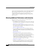
C H A P T E R 2 Using SS7Cfg to Configure Your Gateway Overview For the purposes of this exercise, the following sample network configuration will be used to set up an SS7 Generic (ITU) gateway using SS7Cfg. Note The example exercise configures the network interface from the bottom up, which is consistent with the way SS7Cfg was defined. (Notice that only Gateway 1 will be configured in this example.) In Figure 2-1, Gateway 1 has four links connecting to two different Signal Transfer Points (STPs).
Chapter 2 Using SS7Cfg to Configure Your Gateway STP PC 10 SSP1 PC 200 STP PC 11 SSP2 PC 201 Starting SS7Cfg Figure 2-1 SS7 Gateway Links Gateway 1 PC 150 37785 Gateway 2 PC 151 Starting SS7Cfg Start SS7Cfg by following the instructions below. How to start SS7Cfg Step 1 Click Start > Run and type the following path in the Open field: \icm\bin\ss7cfg If ICM software is installed on a different drive, you may need to preface the above command with a drive letter; for example, d:\icm\bin\ss7cfg.
Chapter 2 Using SS7Cfg to Configure Your Gateway Working in the Main Window You can select one of the following gateways: • INAP (ITU): Used mostly for existing European installations • AIN (ANSI): Used for U.S. IN installations • CRP (ITU): Used for Concert (U.K.) installations • CRP (ANSI/AT&T): Used for U.S.
Chapter 2 Using SS7Cfg to Configure Your Gateway Working in the Main Window Figure 2-2 Note SS7Cfg Main Window The TCAP layer does not have configuration information in the Generic models. For architectural reasons, the configuration of the TCAP and the INAP layers is done on the NIC, and not on the gateway for these gateway types. Notice that the title bar displays “Untitled.
Chapter 2 Using SS7Cfg to Configure Your Gateway Working in the Main Window Configuring the MTP2 Layer In the MTP2 layer, you can configure the link level operating parameters for a gateway. How to configure the MTP2 layer Step 1 Expand the MTP2 layer and the main window displays the following configurable parameters. The following example displays information about a timer. The value might require modification based on the bit rate.
Chapter 2 Using SS7Cfg to Configure Your Gateway Working in the Main Window The check mark next to the Use Default option signifies that this parameter will use the default setting. If you do not want to use the default setting for this parameter, select the Modify option. Note Step 3 The default values for each parameter are usually sufficient for most installations.
Chapter 2 Using SS7Cfg to Configure Your Gateway Working in the Main Window Step 4 If you do not want to use the default setting, select the Modify option, which displays the Configure T1 Timer dialog box to update the timer’s value. Next, the MTP3 layer will be configured. Configuring the MTP3 Layer In the MTP3 layer, you can group links into linksets and define routes for particular network destinations. After expanding the MTP3 layer, the main window displays the following configurable parameters.
Chapter 2 Using SS7Cfg to Configure Your Gateway Working in the Main Window In the following example, the links for Gateway 1 (see Figure 2-1) will be configured, then combined into two linksets (STP1 and STP2), and the routes to the SSPs (SSP1 and SSP2) will be defined. Note Some of the dialog boxes in this process contain Back and Cancel buttons, which allow you to return to the previous dialog box or cancel out of the process, respectively. Begin by configuring the Local Point Code (LPC).
Chapter 2 Using SS7Cfg to Configure Your Gateway Working in the Main Window The Edit Local Point Code (LPC) dialog box displays. The LPC can be assigned with one of the following formats: • Decimal • Hexadecimal Step 2 Enter the point code and click the format type. For our example, the LPC for Gateway 1 is configured as 150 decimal. Step 3 Click OK to return to the main window. Cisco ICM Enterprise Edition SS7 Gateway Configuration Tool User Guide Release 6.
Chapter 2 Using SS7Cfg to Configure Your Gateway Working in the Main Window How to add links Step 1 Right-click the Links parameter and select the Add New Link option from the shortcut menu. Step 2 Our example requires four links. Add the links by selecting the Add New Link option three more times. The main window then displays the following information. Cisco ICM Enterprise Edition SS7 Gateway Configuration Tool User Guide Release 6.
Chapter 2 Using SS7Cfg to Configure Your Gateway Working in the Main Window Next, combine the links into linksets. How to create linksets Step 1 Right-click the Linksets parameter and select the Add New Linkset option from the shortcut menu. Cisco ICM Enterprise Edition SS7 Gateway Configuration Tool User Guide Release 6.
Chapter 2 Using SS7Cfg to Configure Your Gateway Working in the Main Window The Add New Linkset 1 - Remote Point Code (RPC) dialog box appears. Step 2 Click the Edit Remote Point Code button to display the following dialog box. Cisco ICM Enterprise Edition SS7 Gateway Configuration Tool User Guide Release 6.
Chapter 2 Using SS7Cfg to Configure Your Gateway Working in the Main Window Step 3 Define the Remote Point Code (RPC) for the first STP by typing 10 in the Enter New Point Code text box and clicking OK. After returning to the Add New Linkset 1 dialog box, click Next. Step 4 The Add New Linkset 1 - Links in Linkset dialog box appears. Assign links 1 and 2 to this linkset by selecting the link and then clicking the left arrow button. Step 5 Click Next. Now the linkset must be configured.
Chapter 2 Using SS7Cfg to Configure Your Gateway Working in the Main Window This process automatically configures the SLC and the priorities for each link as shown below. Cisco ICM Enterprise Edition SS7 Gateway Configuration Tool User Guide Release 6.
Chapter 2 Using SS7Cfg to Configure Your Gateway Working in the Main Window Step 7 Click Finish. The main window looks like the following. Step 8 To generate the linkset for the second STP, repeat the previous steps using links 3 and 4. After completing this process, the main window looks like the following. Cisco ICM Enterprise Edition SS7 Gateway Configuration Tool User Guide Release 6.
Chapter 2 Using SS7Cfg to Configure Your Gateway Working in the Main Window How to define routes After defining the LPC and creating the links and linksets, finish configuring the MTP3 layer by defining the routes to the SSPs. Step 1 Right-click the Routes parameter and select the Add New Route option from the shortcut menu. Cisco ICM Enterprise Edition SS7 Gateway Configuration Tool User Guide Release 6.
Chapter 2 Using SS7Cfg to Configure Your Gateway Working in the Main Window The Add Route 1 - to Destination PC (DPC): 0 / 0x0 dialog box displays. Cisco ICM Enterprise Edition SS7 Gateway Configuration Tool User Guide Release 6.
Chapter 2 Using SS7Cfg to Configure Your Gateway Working in the Main Window Step 2 Click the Edit DPC button to display the Edit Route Destination Point Code (DPC) dialog box. Define the route destination point in decimal or hexadecimal format, then click OK. Step 3 Right-click in the Configuration area and select the Add new configuration entry option from the shortcut menu. The Edit Route Entry dialog box displays. Cisco ICM Enterprise Edition SS7 Gateway Configuration Tool User Guide Release 6.
Chapter 2 Using SS7Cfg to Configure Your Gateway Working in the Main Window Step 4 Define the route entry for the first linkset. Step 5 Click OK, then repeat the process for the second linkset. This will cause traffic for SSP1 (PC 200) to be sent over the first linkset, if possible. As an alternative, it can be routed over the second linkset. When both route entries are defined, the dialog box displays as shown below. Step 6 Click OK to return to the main window.
Chapter 2 Using SS7Cfg to Configure Your Gateway Working in the Main Window Now the same process needs to be repeated for SSP2 using the links to the second STP as the primary route. When finished, the main window displays the following information. Next, define the local and remote subsystems within the SCCP layer.
Chapter 2 Using SS7Cfg to Configure Your Gateway Working in the Main Window How to define the remote subsystems Next, define the remote subsystem numbers. Step 1 Right-click the Remote Point Codes parameter and select the Add New Remote PC option from the shortcut menu. Cisco ICM Enterprise Edition SS7 Gateway Configuration Tool User Guide Release 6.
Chapter 2 Using SS7Cfg to Configure Your Gateway Working in the Main Window The Add Remote Point Code dialog box displays. Step 2 Click the Edit RPC and Edit SSN buttons to define the remote point codes and subsystem numbers that SCCP will test for and support. In this case, a subsystem of 220 is defined at the SSP with a point code of 200. After both SSPs are defined, the main window will display as shown below. Cisco ICM Enterprise Edition SS7 Gateway Configuration Tool User Guide Release 6.
Chapter 2 Using SS7Cfg to Configure Your Gateway Working in the Main Window How to configure the SCCP global title Some SS7 networks require messages sent from the gateway to be routed with a global title. The configuration of this capability is done at the SCCP level. SCCP routing must first be defined as shown in the previous section, as global title routing can only be configured to use these routes. To configure the global title, you must first define a table.
Chapter 2 Using SS7Cfg to Configure Your Gateway Working in the Main Window The Global Title Table dialog box displays. The Global Title Table dialog box allows you to define the type of global title routing and the parameters that will be associated with it. Step 2 Enter the table information and click OK. The main window now displays the new table as shown below. Cisco ICM Enterprise Edition SS7 Gateway Configuration Tool User Guide Release 6.
Chapter 2 Using SS7Cfg to Configure Your Gateway Working in the Main Window The next step is to define the specific entries that will define where address digit strings will be routed. Step 3 Right-click the Table Type entry and select the Add Entry option from the shortcut menu. Cisco ICM Enterprise Edition SS7 Gateway Configuration Tool User Guide Release 6.
Chapter 2 Using SS7Cfg to Configure Your Gateway Working in the Main Window The GT Table Entry dialog box displays. Step 4 Define a digit string. In this example, “011D” is defined to route to PC 200 as a primary subsystem and PC 201 as a secondary subsystem. This signifies that any of the following digit strings will be routed as 011, 011000, 0115551111, etc. Step 5 Click OK. Generate a second route for the digit strings that do not match the previous criteria.
Chapter 2 Using SS7Cfg to Configure Your Gateway Working in the Main Window This process signifies that outbound SCCP messages with a called number string beginning with “011” will be routed to PC 200 as a primary destination, and all other messages will be routed to PC 201 as a secondary destination. Now that the SCCP layer has been configured, the session layer needs to be configured. Configuring the Session Layer The Session layer controls the interface between the ICM NIC and the gateway.
Chapter 2 Using SS7Cfg to Configure Your Gateway Working in the Main Window After expanding the Session layer, the main window displays the IP Address and Port number parameters. How to define the IP address Step 1 Right-click the IP Address parameter and select the Modify option from the shortcut menu. Cisco ICM Enterprise Edition SS7 Gateway Configuration Tool User Guide Release 6.
Chapter 2 Using SS7Cfg to Configure Your Gateway Working in the Main Window The Edit IP Address dialog box displays. Step 2 Enter the IP address. Note that the gateway’s IP address can be configured as either a dotted IP address or a network computer name. For most configurations (and for this example), the IP address will be entered as a computer name providing the name is in the host’s file. If you prefer a dotted IP address, click the Dotted IP Format check box.
Chapter 2 Using SS7Cfg to Configure Your Gateway Working in the Main Window How to define the port number Step 1 Right-click the Port number parameter and select the Modify option from the shortcut menu. The Edit Port Number dialog box displays. Step 2 Enter the port number. Step 3 Click OK to return to the main window. After defining the port number, the Session layer displays as shown below. Cisco ICM Enterprise Edition SS7 Gateway Configuration Tool User Guide Release 6.
Chapter 2 Using SS7Cfg to Configure Your Gateway Working in the Main Window How to define the local subsystem number Step 1 Right-click the SSN parameter and select the Modify option from the shortcut menu. Cisco ICM Enterprise Edition SS7 Gateway Configuration Tool User Guide Release 6.
Chapter 2 Using SS7Cfg to Configure Your Gateway Working in the Main Window The SSN dialog box displays. Step 2 Select the supported SSNs from the list box on the right and click the left arrow button. Step 3 Click OK to return to the main window. After defining the local subsystem number, the Session layer displays as shown below. Cisco ICM Enterprise Edition SS7 Gateway Configuration Tool User Guide Release 6.
Chapter 2 Using SS7Cfg to Configure Your Gateway Working in the Main Window How to configure the node Since the gateway is a node in the ICM system, our next step consists of configuring the customer and node name. These two items are required so the gateway can access its Registry configuration values. The customer and node names must match the ones used in the ICM setup program. Step 1 Right-click the Node parameter and select the Modify option from the shortcut menu.
Chapter 2 Using SS7Cfg to Configure Your Gateway Working in the Main Window The Edit Customer and Node names dialog box displays. Step 2 Enter the customer and node names in their respective text boxes. Step 3 Click OK. After setting the values, the configuration needs to be saved as a Registry file (*.reg). The changes will be reflected in the main window, as shown below. Cisco ICM Enterprise Edition SS7 Gateway Configuration Tool User Guide Release 6.
Chapter 2 Using SS7Cfg to Configure Your Gateway Saving the Configuration Saving the Configuration An important feature of SS7Cfg is that you can remotely edit and maintain regedit files (*.reg) that can then be imported to and exported from the NT Registry with the Windows regedit utility, without involving the ICM gateway site. Note Do not use files exported from Regedt32 because they use a different format for exported Registry files that is incompatible with the format for regedit files.
Chapter 2 Using SS7Cfg to Configure Your Gateway Saving the Configuration Step 2 The Save As dialog box displays. Enter the file name and select the SS7Cfg Files (*.reg) file type. At this point, the system performs a consistency check against the Registry file. For example, if there are no routes defined for the Remote Point Codes defined at MTP3, a message box displays asking if you would like to continue with the error, or go back and fix it. (One message box will display for each error detected.
Chapter 2 Using SS7Cfg to Configure Your Gateway Importing the Registry File In this case, clicking OK will save the configuration with errors to disk. Clicking Cancel will cancel the file save operation and allow you to continue editing to fix the configuration problem. Importing the Registry File Now that the gateway configuration has been saved as a Registry file, the final step of the configuration process can be performed by importing the file into the Registry using the regedit utility.
Chapter 2 Using SS7Cfg to Configure Your Gateway Importing the Registry File Step 3 Within this window, drill down to the HKEY_LOCAL_MACHINE\SOFTWARE\Cisco Systems, Inc.\ICM\\\SS7Gate folder. Step 4 Right-click the CurrentVersion registry key to display the following shortcut menu. Cisco ICM Enterprise Edition SS7 Gateway Configuration Tool User Guide Release 6.
Chapter 2 Using SS7Cfg to Configure Your Gateway Importing the Registry File Step 5 Select Rename and change the keyname to one that describes the save date, backup000329, as shown below. Note Step 6 If you are performing multiple updates during the day, you could use backupYYMMDD_HHMM as the keyname to display the exact time each save occurred. Select Registry > Import Registry File from the menu bar, as shown below. Cisco ICM Enterprise Edition SS7 Gateway Configuration Tool User Guide Release 6.
Chapter 2 Using SS7Cfg to Configure Your Gateway Importing the Registry File The Import Registry File dialog box displays the Registry file saved earlier using SS7Cfg. Step 7 Click Open. The regedit utility imports the file into the Registry and completes the gateway configuration process. Now when you import the new Registry file you will have multiple instances, as shown below. Cisco ICM Enterprise Edition SS7 Gateway Configuration Tool User Guide Release 6.
Chapter 2 Using SS7Cfg to Configure Your Gateway Using SS7Cfg to Directly Manipulate the Registry Only the keys and values under CurrentVersion will actually control the SS7 gateway. If the new keys do not work as expected, you can always return to an earlier version by renaming the CurrentVersion key to a backup name and renaming one of the backup names to “CurrentVersion.
Chapter 2 Using SS7Cfg to Configure Your Gateway Using SS7Cfg to Directly Manipulate the Registry A dialog box appears, prompting for a target gateway for export. This information is presented in a tree format, with parent nodes representing the customer names and child nodes displaying gateway nodes present for each customer. Step 2 To export to another machine’s registry, click the Connect to remote computer check box, then enter the machine’s name in the text box.
Chapter 2 Using SS7Cfg to Configure Your Gateway Using SS7Cfg to Directly Manipulate the Registry Step 3 Select a gateway for export by either selecting the gateway instance in the tree and clicking the OK button, or by double-clicking the gateway name in the tree control. The SS7Cfg application determines the selected gateway’s type and verifies that the current configuration matches.
Chapter 2 Using SS7Cfg to Configure Your Gateway Using SS7Cfg to Directly Manipulate the Registry Selecting this option bypasses the customer/node selection dialog box and begins export to the given customer and node. How to import from the Registry One useful result of importing directly from the Registry is the ability to copy settings from another machine located on the network. This is done simply by importing the configuration from a remote machine and then exporting it to the local machine.
Chapter 2 Using SS7Cfg to Configure Your Gateway Using SS7Cfg to Directly Manipulate the Registry A dialog box appears, prompting for a target gateway for import. This information is presented in a tree format, with parent nodes representing the customer names and child nodes displaying gateway nodes present for each customer. Step 2 To import from another machine’s registry, click the Connect to remote computer check box, then enter the machine’s name in the text box.
Chapter 2 Using SS7Cfg to Configure Your Gateway Using SS7Cfg to Directly Manipulate the Registry Cisco ICM Enterprise Edition SS7 Gateway Configuration Tool User Guide Release 6.
INDEX A E adding links 2-10 exporting, directly to Registry 2-41 C G configuring gateway types supported 1-2 global title 2-23 global title, configuring 2-23 LPC 2-8 MTP2 layer 2-5 I MTP3 layer 2-7 node 2-33 importing, directly to Registry 2-44 SCCP layer 2-20 importing Registry file 2-37 Session layer 2-27 IP address, defining 2-28 creating linksets 2-11 L D links, adding 2-10 defining linksets, creating 2-11 IP address 2-28 local subsystem number, defining 2-31 local subsystem numb
Index MTP3 layer, configuring 2-7 T terminology 1-2 N node, configuring 2-33 P port number, defining 2-30 R Registry exporting directly 2-41 importing directly 2-44 Registry file, importing 2-37 remote subsystems, defining 2-21 routes, defining 2-16 S saving configuration 2-35 SCCP layer, configuring 2-20 selecting gateway type 2-3 Session layer, configuring 2-27 starting SS7Cfg 2-2 Cisco ICM Enterprise Edition SS7 Gateway Configuration Tool User Guide Release 6.