
user manual


Table Of Contents
- User Guide for Internetwork Performance Monitor
- Contents
- Preface
- Overview of IPM
- Getting Started With IPM
- Using IPM to Measure Network Performance
- Measuring Network Performance for DHCP
- Measuring Network Performance for DLSw
- Measuring Network Performance for DNS
- Measuring Network Performance for HTTP
- Measuring Network Performance for FTP
- Measuring Network Performance for IP
- Measuring Network Performance for SNA
- Measuring Network Performance for TCP
- Measuring Network Performance for UDP
- Measuring Network Performance for Enhanced UDP
- Modifying IPM Components
- Working With Source Devices
- Working With Target Devices
- Working With Operations
- Working With Collectors
- Adding Components Using Seed Files
- Changing IP Addresses
- Setting the Baseline
- Setting IPM Database Preferences
- Setting SNMP Timeout and Retry Environment Variables
- Setting New IPM Server Process Timeout Values
- Setting the DISPLAY Variable in Solaris
- Backing Up or Restoring the IPM Database
- NVRAM Settings
- Managed Source Interface Settings
- Changing Administrative Password
- Changing IPM Database Password
- Working With Message Log Window
- Working With IPM From the CiscoWorks Homepage
- Accessing IPM Data From the CiscoWorks Homepage
- Viewing IPM Server Information
- Importing Devices From Device and Credential Repository
- Downloading the IPM Client
- Viewing Configuration Information
- Viewing Latency Data
- Viewing Jitter Data
- Viewing HTTP Data
- Accessing Software Updates and Additional Information
- IPM FAQs and Troubleshooting Tips
- IPM Command Reference
- SA Agent Feature Mapping
- Glossary
- Index
3-23
User Guide for Internetwork Performance Monitor
OL-11291-01
Chapter 3 Using IPM to Measure Network Performance
Measuring Network Performance for IP
Step 3 Click Path Echo.
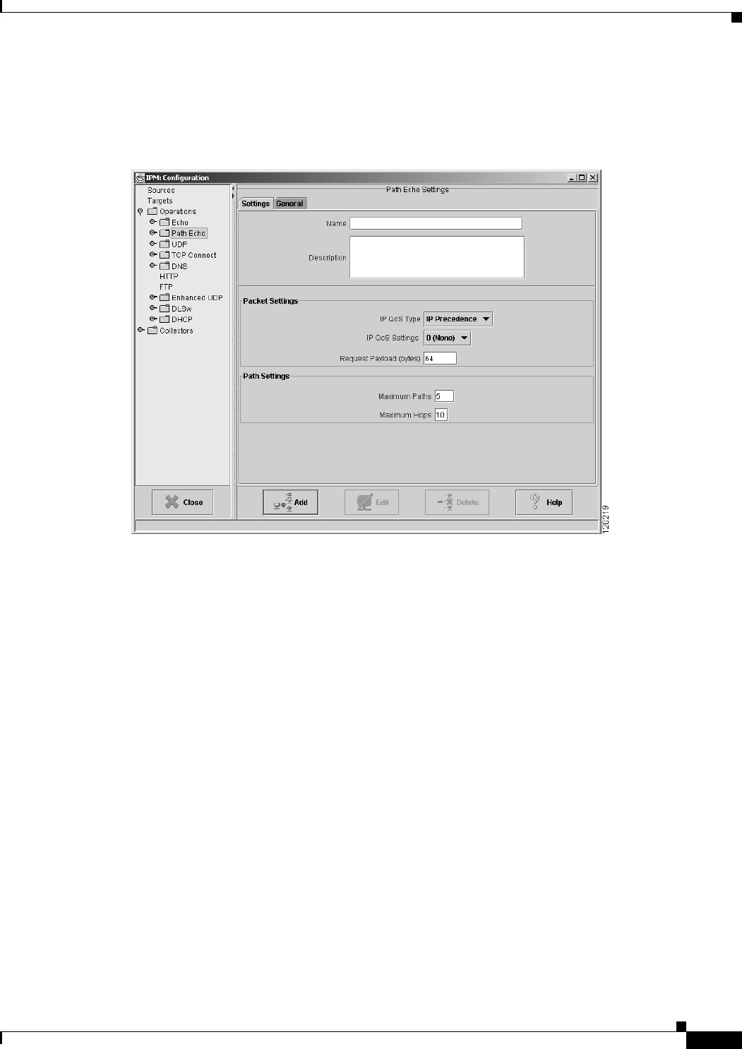
The Path Echo Operation Configuration window (Figure 3-13) appears.
Figure 3-13 IP Path Echo Operation Configuration Window
Step 4 In the Name field, enter a descriptive name to assign to the operation. In the Description field, you can
enter a brief description of the operation, including its purpose.
Step 5 Select the IP QoS Type as IP Precedence or DCSP. The IP QoS Settings values change based on your IP
QoS Type selection.
• If you have selected IP QoS Type as IP Precedence, select the IP QoS Settings value from the
drop-down. The value you select sets the priority for the HTTP request packet. The default setting
is 0 (no priority). This option sets the ToS bits in the IP packet.
• If you have selected IP QoS Type as DSCP, select the desired IP QoS Settings value from the
drop-down. The value you select defines the packet priority and is based on the DSCP RFC
standards.
Step 6 In the Request Payload field, enter the number of bytes to use for the size of the payload of the ICMP
echo request packet. The default setting is 64 bytes.
• To specify the maximum number of paths to discover, enter a value in the Maximum Paths field. The
valid range is 1 to 128 paths. The default setting is 5. To ensure that you do not miss collecting
statistics for relevant paths, set this value to a number slightly higher than the expected number of
paths.
• To specify the maximum number of hops to discover, enter a value in the Maximum Hops field. The
valid range is 1 to 25 hops. The default setting is 25 hops. To ensure that you do not miss collecting
statistics for relevant hops, set this value to a number slightly higher than the expected number of
hops.