
user manual

13-33
Cisco Aironet 1200 Series Access Point Software Configuration Guide
OL-2159-05
Chapter 13 Diagnostics and Troubleshooting
Checking the Top Panel Indicators
Finding an Access Point by Blinking the Top Panel Indicators
If you need to find the physical location of a particular access point, you can put the top panel indicators
into blinking mode. Follow these instructions to blink the access point’s top panel indicators:
Step 1 Browse to the access point’s Cisco Services Setup page:
a. On the Summary Status page, click Setup.
b. On the Setup page, click Cisco Services.
Step 2 Select Enabled for the Locate unit by flashing LEDs option.
Step 3 Click Apply. The access point’s top panel indicators blink amber in unison.
Step 4 To make the indicators stop blinking and return to normal operation, select Disabled for the Locate unit
by flashing LEDs option, and click Apply.
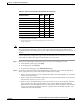
Operational – Steady
green
Blinking
green
Transmitting/receiving
radio packets.
Blinking
green
Steady
green
– Transmitting/receiving
packets.
– Steady
green
Blinking
amber
Maximum retries or
buffer full occurred on
one of the radios.
Error/warning Blinking
amber
Steady
green
– Transmit/receive errors.
– Blinking
amber
– General warning.
Failure Steady
red
Steady
red
Steady
red
Firmware failure;
disconnect power from
the unit and reapply
power.
Firmware
upgrade
– Steady
red
– Unit is loading new
firmware.
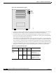
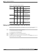
Table 13-3 Top Panel Indicator Signals (continued)
Message
type
Ethernet
indicator
Status
indicator
Radio
indicator
Meaning