
user manual


Table Of Contents
- Cisco ASR 9000 Series Aggregation Services Router Overview and Reference Guide
- Preface
- Overview and Physical Description
- Chassis Physical Overview
- Cisco ASR 9010 Router
- Cisco ASR 9006 Router
- Cisco ASR 9904 Router
- Cisco ASR 9922 Router
- Cisco ASR 9912 Router
- Field Replaceable Units
- Rack-Mounting Considerations
- Chassis Slots
- Fiber and Interface Cable Management
- Routing of DC Power Tray Source Cables
- Slot Numbering and Marking
- Power Module Hardware and Software Identification
- Route Switch Processor and Route Processor Cards
- RSP Front Panel and Access Ports
- RP Front Panel and Access Ports
- Management Features
- Alarm Connector
- Serviceability
- RSP and RP Card Ejector Levers
- Fabric Controller Card
- FC Card Ejector Levers
- Ethernet Line Cards
- Line Card Front Panel and Access Ports
- Line Card Serviceability
- Line Card Ejector Levers
- Power System
- AC and DC Power Modules
- Cooling System
- Cooling Path
- Fan Trays
- Management and Configuration
- Line Card Front Panel and Access Ports
- Line Card Serviceability
- Line Card Ejector Levers
- Power System
- Functional Description
- Router Operation
- Route Switch Processor Card
- Route Processor Card
- Front Panel Connectors
- Management LAN Ports
- Console Port
- Auxiliary Port
- Alarm Out
- Synchronization Ports
- RP USB Port
- Front Panel Indicators
- LED Matrix Display
- LED Matrix Boot Stage and Runtime Display
- LED Matrix CAN Bus Controller Error Display
- Push Buttons
- Functional Description
- Switch Fabric
- Unicast Traffic
- Multicast Traffic
- Route Processor Functions
- Processor-to-Processor Communication
- Route Processor/Fabric Interconnect
- Fabric Controller Card
- FC Card Front Panel Indicator
- Ethernet Line Cards
- Functional Description
- 40-Port Gigabit Ethernet (40x1GE) Line Card
- 8-Port 10-Gigabit Ethernet (8x10GE) 2:1 Oversubscribed Line Card
- 4-Port 10-Gigabit Ethernet (4x10GE) Line Card
- 8-port 10-Gigabit Ethernet (8x10GE) 80-Gbps Line Rate Card
- 2-Port 10-Gigabit Ethernet + 20-port 1-Gigabit Ethernet (2x10GE + 20x1GE) Combination Line Card
- 16-port 10-Gigabit Ethernet (16x10GE) Oversubscribed Line Card
- 24-Port 10-Gigabit Ethernet Line Card
- 36-port 10-Gigabit Ethernet Line Card
- 2-port 100-Gigabit Ethernet Line Card
- 1-Port 100-Gigabit Ethernet Line Card
- Modular Line Cards
- 20-port Gigabit Ethernet Modular Port Adapter
- 8-port 10-Gigabit Ethernet Modular Port Adapter
- 4-Port 10-Gigabit Ethernet Modular Port Adapter
- 2-port 10-Gigabit Ethernet Modular Port Adapter
- 2-Port 40-Gigabit Ethernet Modular Port Adapter
- 1-Port 40-Gigabit Ethernet Modular Port Adapter
- Power System Functional Description
- Power Modules
- Power Module Status Indicators
- System Power Redundancy
- AC Power Trays
- AC Tray Power Switch
- AC Input Voltage Range
- DC Output Levels
- AC System Operation
- Power Up
- Power Down
- DC Power Trays
- DC Tray Power Switch
- DC Power Tray Rear Panel
- DC Power Tray Power Feed Indicator
- DC System Operation
- Power Up
- Power Down
- Cooling System Functional Description
- Cooling Path
- Fan Trays
- Cisco ASR 9010 Router Fan Trays
- Cisco ASR 9006 Router Fan Trays
- Cisco ASR 9904 Router Fan Tray
- Cisco ASR 9922 Router and Cisco ASR 9912 Router Fan Trays
- Status Indicators
- Fan Tray Servicing
- Slot Fillers
- Chassis Air Filter
- Speed Control
- Temperature Sensing and Monitoring
- Servicing
- System Shutdown
- System Management and Configuration
- Cisco IOS XR Software
- System Management Interfaces
- Command-Line Interface
- Craft Works Interface
- XML
- SNMP
- SNMP Agent
- MIBs
- Online Diagnostics
- High Availability and Redundant Operation
- Features Overview
- High Availability Router Operations
- Stateful Switchover
- Fabric Switchover
- Active/Standby Status Interpretation
- Non-Stop Forwarding
- Nonstop Routing
- Graceful Restart
- Process Restartability
- Fault Detection and Management
- Power Supply Redundancy
- AC Power Redundancy
- DC Power Redundancy
- Detection and Reporting of Power Problems
- Cooling System Redundancy
- Cooling Failure Alarm
- Technical Specifications
2-17
Cisco ASR 9000 Series Aggregation Services Router Overview and Reference Guide
OL-17501-09
Chapter 2 Functional Description
Route Processor Card
The switch fabric has the capability to replicate multicast packets to downlink egress ports. In addition,
the line cards have the capability to put multiple copies inside different tunnels or attachment circuits in
a single port.
There are 64-K Fabric Multicast Groups (RSP 2-based line cards) or 128-K Fabric Multicast Groups
(RSP 440-based line cards) in the system, which allow the replication to go only to the downlink paths
that need them, without sending all multicast traffic to every packet processor. Each multicast group in
the system can be configured as to which line card and which packet processor on that card a packet is
replicated to. Multicast is not arbitrated by the VOQ mechanism, but it is subject to arbitration at
congestion points within the switch fabric.
Route Processor Functions
The Route Processor performs the ordinary chassis management functions. The ASR 9000 Series
Routers run Cisco IOS XR software, so the Route Processor runs the centralized portions of the software
for chassis control and management.
Secondary functions of the Route Processor include boot media, system timing (frequency and time of
date) synchronization, precision clock synchronization, backplane Ethernet communication, and power
control (through a separate CAN bus controller network).
The Route Processor communicates with other route processors and linecards over a switched Ethernet
out-of-band channel (EOBC) for management and control purposes.
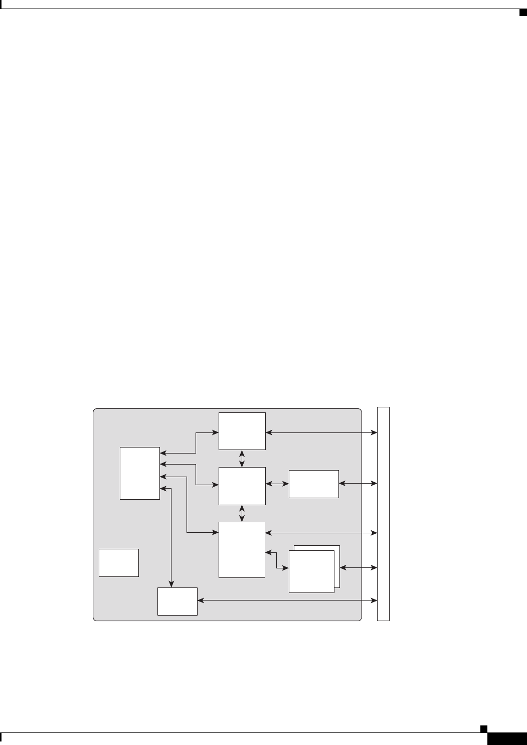
Figure 2-11 shows the route processor interconnections on the RSP.
Figure 2-12 shows the component interconnections on the RP.
Figure 2-13 shows the component interconnections on the FC.
Figure 2-11 Route Processor Interconnections
RSP
243066
B
a
c
k
p
l
a
n
e
Fabric
Interface
Chip
Fabric
Chip
System
Timing
GE
Switch
CPU
Packet
Diversion
FPGA
CPU
Interface
FPGA
VOQ
Scheduler