
user manual


Table Of Contents
- Cisco ASR 9000 Series Aggregation Services Router Overview and Reference Guide
- Preface
- Overview and Physical Description
- Chassis Physical Overview
- Cisco ASR 9010 Router
- Cisco ASR 9006 Router
- Cisco ASR 9904 Router
- Cisco ASR 9922 Router
- Cisco ASR 9912 Router
- Field Replaceable Units
- Rack-Mounting Considerations
- Chassis Slots
- Fiber and Interface Cable Management
- Routing of DC Power Tray Source Cables
- Slot Numbering and Marking
- Power Module Hardware and Software Identification
- Route Switch Processor and Route Processor Cards
- RSP Front Panel and Access Ports
- RP Front Panel and Access Ports
- Management Features
- Alarm Connector
- Serviceability
- RSP and RP Card Ejector Levers
- Fabric Controller Card
- FC Card Ejector Levers
- Ethernet Line Cards
- Line Card Front Panel and Access Ports
- Line Card Serviceability
- Line Card Ejector Levers
- Power System
- AC and DC Power Modules
- Cooling System
- Cooling Path
- Fan Trays
- Management and Configuration
- Line Card Front Panel and Access Ports
- Line Card Serviceability
- Line Card Ejector Levers
- Power System
- Functional Description
- Router Operation
- Route Switch Processor Card
- Route Processor Card
- Front Panel Connectors
- Management LAN Ports
- Console Port
- Auxiliary Port
- Alarm Out
- Synchronization Ports
- RP USB Port
- Front Panel Indicators
- LED Matrix Display
- LED Matrix Boot Stage and Runtime Display
- LED Matrix CAN Bus Controller Error Display
- Push Buttons
- Functional Description
- Switch Fabric
- Unicast Traffic
- Multicast Traffic
- Route Processor Functions
- Processor-to-Processor Communication
- Route Processor/Fabric Interconnect
- Fabric Controller Card
- FC Card Front Panel Indicator
- Ethernet Line Cards
- Functional Description
- 40-Port Gigabit Ethernet (40x1GE) Line Card
- 8-Port 10-Gigabit Ethernet (8x10GE) 2:1 Oversubscribed Line Card
- 4-Port 10-Gigabit Ethernet (4x10GE) Line Card
- 8-port 10-Gigabit Ethernet (8x10GE) 80-Gbps Line Rate Card
- 2-Port 10-Gigabit Ethernet + 20-port 1-Gigabit Ethernet (2x10GE + 20x1GE) Combination Line Card
- 16-port 10-Gigabit Ethernet (16x10GE) Oversubscribed Line Card
- 24-Port 10-Gigabit Ethernet Line Card
- 36-port 10-Gigabit Ethernet Line Card
- 2-port 100-Gigabit Ethernet Line Card
- 1-Port 100-Gigabit Ethernet Line Card
- Modular Line Cards
- 20-port Gigabit Ethernet Modular Port Adapter
- 8-port 10-Gigabit Ethernet Modular Port Adapter
- 4-Port 10-Gigabit Ethernet Modular Port Adapter
- 2-port 10-Gigabit Ethernet Modular Port Adapter
- 2-Port 40-Gigabit Ethernet Modular Port Adapter
- 1-Port 40-Gigabit Ethernet Modular Port Adapter
- Power System Functional Description
- Power Modules
- Power Module Status Indicators
- System Power Redundancy
- AC Power Trays
- AC Tray Power Switch
- AC Input Voltage Range
- DC Output Levels
- AC System Operation
- Power Up
- Power Down
- DC Power Trays
- DC Tray Power Switch
- DC Power Tray Rear Panel
- DC Power Tray Power Feed Indicator
- DC System Operation
- Power Up
- Power Down
- Cooling System Functional Description
- Cooling Path
- Fan Trays
- Cisco ASR 9010 Router Fan Trays
- Cisco ASR 9006 Router Fan Trays
- Cisco ASR 9904 Router Fan Tray
- Cisco ASR 9922 Router and Cisco ASR 9912 Router Fan Trays
- Status Indicators
- Fan Tray Servicing
- Slot Fillers
- Chassis Air Filter
- Speed Control
- Temperature Sensing and Monitoring
- Servicing
- System Shutdown
- System Management and Configuration
- Cisco IOS XR Software
- System Management Interfaces
- Command-Line Interface
- Craft Works Interface
- XML
- SNMP
- SNMP Agent
- MIBs
- Online Diagnostics
- High Availability and Redundant Operation
- Features Overview
- High Availability Router Operations
- Stateful Switchover
- Fabric Switchover
- Active/Standby Status Interpretation
- Non-Stop Forwarding
- Nonstop Routing
- Graceful Restart
- Process Restartability
- Fault Detection and Management
- Power Supply Redundancy
- AC Power Redundancy
- DC Power Redundancy
- Detection and Reporting of Power Problems
- Cooling System Redundancy
- Cooling Failure Alarm
- Technical Specifications
1-18
Cisco ASR 9000 Series Aggregation Services Router Overview and Reference Guide
OL-17501-09
Chapter 1 Overview and Physical Description
Rack-Mounting Considerations
Slot Numbering and Marking
All card slots are clearly numbered. Labels identifying slots are visible from the front of the chassis and
are clearly numbered below each slot. As mentioned previously, fiber and cables are routed upward and
do not obscure the slot ID labels.
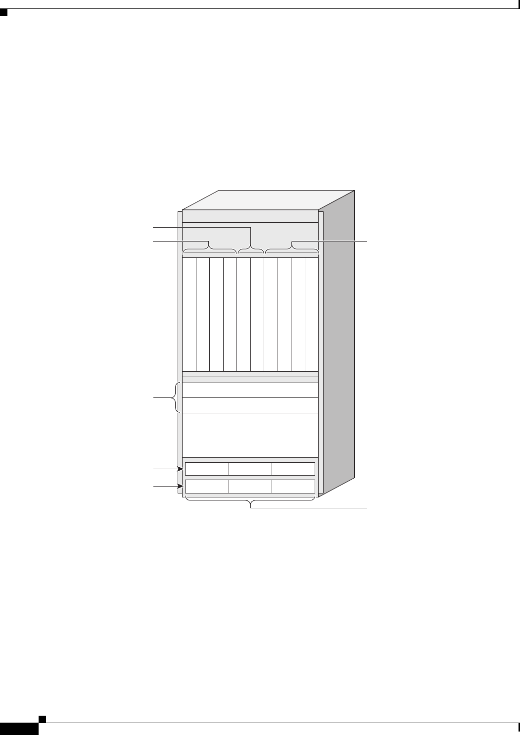
Figure 1-16 shows slot ID numbering for the Cisco ASR 9010 Router with version 1 power trays.
Figure 1-17 shows slot ID numbering for the Cisco ASR 9010 Router with version 2 power trays.
Figure 1-16 Cisco ASR 9010 Router Router Slot ID Numbering—Version 1 Power Trays
242689
Line card
Line card
Line card
Line card
RSP0
RSP1
FT0
FT1
Front air intake
Line card
Line card
Line card
Line card
Slot 0
Slot 1
Slot 2
Slot 3
Slot 4
Slot 5
Slot 6
Slot 7
Slot 8
Slot 9
Power shelves
PS0
PS1
Power modules
M0 M1 M2
M0 M1 M2
Line cards 0-3
Fan trays
Line cards 4-7
RSP cards
0123 4567