
user manual


Table Of Contents
- Cisco ASR 9000 Series Aggregation Services Router Overview and Reference Guide
- Preface
- Overview and Physical Description
- Chassis Physical Overview
- Cisco ASR 9010 Router
- Cisco ASR 9006 Router
- Cisco ASR 9904 Router
- Cisco ASR 9922 Router
- Cisco ASR 9912 Router
- Field Replaceable Units
- Rack-Mounting Considerations
- Chassis Slots
- Fiber and Interface Cable Management
- Routing of DC Power Tray Source Cables
- Slot Numbering and Marking
- Power Module Hardware and Software Identification
- Route Switch Processor and Route Processor Cards
- RSP Front Panel and Access Ports
- RP Front Panel and Access Ports
- Management Features
- Alarm Connector
- Serviceability
- RSP and RP Card Ejector Levers
- Fabric Controller Card
- FC Card Ejector Levers
- Ethernet Line Cards
- Line Card Front Panel and Access Ports
- Line Card Serviceability
- Line Card Ejector Levers
- Power System
- AC and DC Power Modules
- Cooling System
- Cooling Path
- Fan Trays
- Management and Configuration
- Line Card Front Panel and Access Ports
- Line Card Serviceability
- Line Card Ejector Levers
- Power System
- Functional Description
- Router Operation
- Route Switch Processor Card
- Route Processor Card
- Front Panel Connectors
- Management LAN Ports
- Console Port
- Auxiliary Port
- Alarm Out
- Synchronization Ports
- RP USB Port
- Front Panel Indicators
- LED Matrix Display
- LED Matrix Boot Stage and Runtime Display
- LED Matrix CAN Bus Controller Error Display
- Push Buttons
- Functional Description
- Switch Fabric
- Unicast Traffic
- Multicast Traffic
- Route Processor Functions
- Processor-to-Processor Communication
- Route Processor/Fabric Interconnect
- Fabric Controller Card
- FC Card Front Panel Indicator
- Ethernet Line Cards
- Functional Description
- 40-Port Gigabit Ethernet (40x1GE) Line Card
- 8-Port 10-Gigabit Ethernet (8x10GE) 2:1 Oversubscribed Line Card
- 4-Port 10-Gigabit Ethernet (4x10GE) Line Card
- 8-port 10-Gigabit Ethernet (8x10GE) 80-Gbps Line Rate Card
- 2-Port 10-Gigabit Ethernet + 20-port 1-Gigabit Ethernet (2x10GE + 20x1GE) Combination Line Card
- 16-port 10-Gigabit Ethernet (16x10GE) Oversubscribed Line Card
- 24-Port 10-Gigabit Ethernet Line Card
- 36-port 10-Gigabit Ethernet Line Card
- 2-port 100-Gigabit Ethernet Line Card
- 1-Port 100-Gigabit Ethernet Line Card
- Modular Line Cards
- 20-port Gigabit Ethernet Modular Port Adapter
- 8-port 10-Gigabit Ethernet Modular Port Adapter
- 4-Port 10-Gigabit Ethernet Modular Port Adapter
- 2-port 10-Gigabit Ethernet Modular Port Adapter
- 2-Port 40-Gigabit Ethernet Modular Port Adapter
- 1-Port 40-Gigabit Ethernet Modular Port Adapter
- Power System Functional Description
- Power Modules
- Power Module Status Indicators
- System Power Redundancy
- AC Power Trays
- AC Tray Power Switch
- AC Input Voltage Range
- DC Output Levels
- AC System Operation
- Power Up
- Power Down
- DC Power Trays
- DC Tray Power Switch
- DC Power Tray Rear Panel
- DC Power Tray Power Feed Indicator
- DC System Operation
- Power Up
- Power Down
- Cooling System Functional Description
- Cooling Path
- Fan Trays
- Cisco ASR 9010 Router Fan Trays
- Cisco ASR 9006 Router Fan Trays
- Cisco ASR 9904 Router Fan Tray
- Cisco ASR 9922 Router and Cisco ASR 9912 Router Fan Trays
- Status Indicators
- Fan Tray Servicing
- Slot Fillers
- Chassis Air Filter
- Speed Control
- Temperature Sensing and Monitoring
- Servicing
- System Shutdown
- System Management and Configuration
- Cisco IOS XR Software
- System Management Interfaces
- Command-Line Interface
- Craft Works Interface
- XML
- SNMP
- SNMP Agent
- MIBs
- Online Diagnostics
- High Availability and Redundant Operation
- Features Overview
- High Availability Router Operations
- Stateful Switchover
- Fabric Switchover
- Active/Standby Status Interpretation
- Non-Stop Forwarding
- Nonstop Routing
- Graceful Restart
- Process Restartability
- Fault Detection and Management
- Power Supply Redundancy
- AC Power Redundancy
- DC Power Redundancy
- Detection and Reporting of Power Problems
- Cooling System Redundancy
- Cooling Failure Alarm
- Technical Specifications
A-13
Cisco ASR 9000 Series Aggregation Services Router Overview and Reference Guide
OL-17501-09
Appendix A Technical Specifications
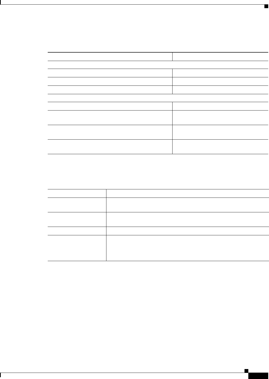
Table A-20 lists the DC output tolerances for AC or DC power modules for the version 2 power system.
Table A-21 lists the RSP/RP port specifications.
Table A-20 DC Output Levels for Version 2 Power System
Parameter Value
Voltage
Maximum –55.5 VDC
Nominal –54.0 VDC
Minimum –52.5 VDC
Power
Minimum (one power module) 2100 W
Maximum (four 2100 W power modules in a single tray)
1
1. Maximum output power the power system is capable of supporting (not system power consumption).
8400 W (Cisco ASR 9006 Router and
Cisco ASR 9904 Router)
Maximum (four 2100 W power modules per tray x two
trays)
16,800 W (Cisco ASR 9010 Router only)
Maximum (four 2100 W power modules per tray x four
trays)
33,600 W (Cisco ASR 9922 Router only)
Table A-21 RSP/RP Port Specifications
Description Value
Console port EIA/TIA-232 RJ-45 interface, 9600 Baud, 8 data, no parity, 2 stop bits with
flow control none (default)
Auxiliary port EIA/TIA-232 RJ-45 interface, 9600 Baud, 8 data, no parity, 1 stop bit with
software handshake (default)
Management ports (0, 1) Dual-speed (100M/1000M) RJ-45
Sync ports (0, 1) Can be configured as one of the following:
• BITS (Building Integrated Timing System) port
• J.211 or UTI (Universal Timing Interface) port