
user manual
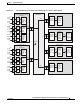


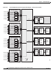
Table Of Contents
- Cisco ASR 9000 Series Aggregation Services Router Overview and Reference Guide
- Preface
- Overview and Physical Description
- Chassis Physical Overview
- Cisco ASR 9010 Router
- Cisco ASR 9006 Router
- Cisco ASR 9904 Router
- Cisco ASR 9922 Router
- Cisco ASR 9912 Router
- Field Replaceable Units
- Rack-Mounting Considerations
- Chassis Slots
- Fiber and Interface Cable Management
- Routing of DC Power Tray Source Cables
- Slot Numbering and Marking
- Power Module Hardware and Software Identification
- Route Switch Processor and Route Processor Cards
- RSP Front Panel and Access Ports
- RP Front Panel and Access Ports
- Management Features
- Alarm Connector
- Serviceability
- RSP and RP Card Ejector Levers
- Fabric Controller Card
- FC Card Ejector Levers
- Ethernet Line Cards
- Line Card Front Panel and Access Ports
- Line Card Serviceability
- Line Card Ejector Levers
- Power System
- AC and DC Power Modules
- Cooling System
- Cooling Path
- Fan Trays
- Management and Configuration
- Line Card Front Panel and Access Ports
- Line Card Serviceability
- Line Card Ejector Levers
- Power System
- Functional Description
- Router Operation
- Route Switch Processor Card
- Route Processor Card
- Front Panel Connectors
- Management LAN Ports
- Console Port
- Auxiliary Port
- Alarm Out
- Synchronization Ports
- RP USB Port
- Front Panel Indicators
- LED Matrix Display
- LED Matrix Boot Stage and Runtime Display
- LED Matrix CAN Bus Controller Error Display
- Push Buttons
- Functional Description
- Switch Fabric
- Unicast Traffic
- Multicast Traffic
- Route Processor Functions
- Processor-to-Processor Communication
- Route Processor/Fabric Interconnect
- Fabric Controller Card
- FC Card Front Panel Indicator
- Ethernet Line Cards
- Functional Description
- 40-Port Gigabit Ethernet (40x1GE) Line Card
- 8-Port 10-Gigabit Ethernet (8x10GE) 2:1 Oversubscribed Line Card
- 4-Port 10-Gigabit Ethernet (4x10GE) Line Card
- 8-port 10-Gigabit Ethernet (8x10GE) 80-Gbps Line Rate Card
- 2-Port 10-Gigabit Ethernet + 20-port 1-Gigabit Ethernet (2x10GE + 20x1GE) Combination Line Card
- 16-port 10-Gigabit Ethernet (16x10GE) Oversubscribed Line Card
- 24-Port 10-Gigabit Ethernet Line Card
- 36-port 10-Gigabit Ethernet Line Card
- 2-port 100-Gigabit Ethernet Line Card
- 1-Port 100-Gigabit Ethernet Line Card
- Modular Line Cards
- 20-port Gigabit Ethernet Modular Port Adapter
- 8-port 10-Gigabit Ethernet Modular Port Adapter
- 4-Port 10-Gigabit Ethernet Modular Port Adapter
- 2-port 10-Gigabit Ethernet Modular Port Adapter
- 2-Port 40-Gigabit Ethernet Modular Port Adapter
- 1-Port 40-Gigabit Ethernet Modular Port Adapter
- Power System Functional Description
- Power Modules
- Power Module Status Indicators
- System Power Redundancy
- AC Power Trays
- AC Tray Power Switch
- AC Input Voltage Range
- DC Output Levels
- AC System Operation
- Power Up
- Power Down
- DC Power Trays
- DC Tray Power Switch
- DC Power Tray Rear Panel
- DC Power Tray Power Feed Indicator
- DC System Operation
- Power Up
- Power Down
- Cooling System Functional Description
- Cooling Path
- Fan Trays
- Cisco ASR 9010 Router Fan Trays
- Cisco ASR 9006 Router Fan Trays
- Cisco ASR 9904 Router Fan Tray
- Cisco ASR 9922 Router and Cisco ASR 9912 Router Fan Trays
- Status Indicators
- Fan Tray Servicing
- Slot Fillers
- Chassis Air Filter
- Speed Control
- Temperature Sensing and Monitoring
- Servicing
- System Shutdown
- System Management and Configuration
- Cisco IOS XR Software
- System Management Interfaces
- Command-Line Interface
- Craft Works Interface
- XML
- SNMP
- SNMP Agent
- MIBs
- Online Diagnostics
- High Availability and Redundant Operation
- Features Overview
- High Availability Router Operations
- Stateful Switchover
- Fabric Switchover
- Active/Standby Status Interpretation
- Non-Stop Forwarding
- Nonstop Routing
- Graceful Restart
- Process Restartability
- Fault Detection and Management
- Power Supply Redundancy
- AC Power Redundancy
- DC Power Redundancy
- Detection and Reporting of Power Problems
- Cooling System Redundancy
- Cooling Failure Alarm
- Technical Specifications
2-62
Cisco ASR 9000 Series Aggregation Services Router Overview and Reference Guide
OL-17501-09
Chapter 2 Functional Description
Power System Functional Description
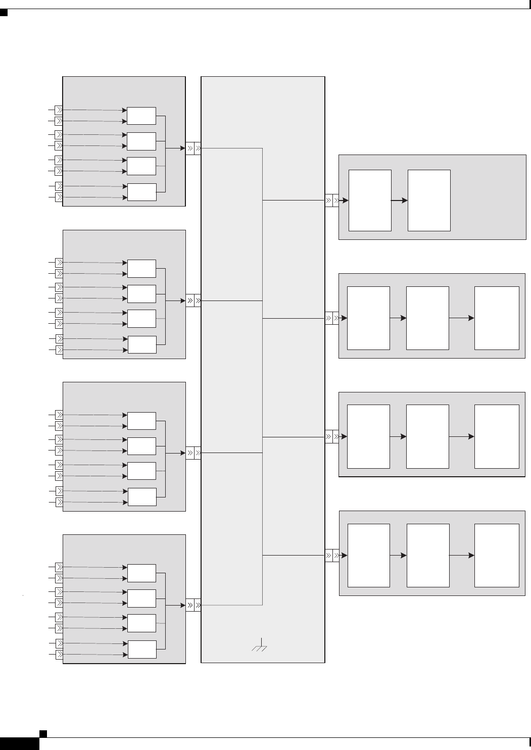
Figure 2-52 Cisco ASR 9922 Router DC Power System Block Diagram—Version 2 Power System
Fan Tray (x4)
Power Distribution
DC Power Shelf-0 w/DC/DC 2KW
Power Supply Modules
Soft-Start
Circuit,
EMI
Filter, and
Fan
Controller
Line Card (x20)
Narrow
Range,
Fixed
Ratio
(5:1)
10.8V
Converter
Soft-Start
Circuit,
EMI
Filter, and
Fan
Controller
Point of
Load
(POL)
Converters
-54V
-10.8V
Cooling
Fans
-54V
Route Processor (x2)
Narrow
Range,
Fixed
Ratio
(5:1)
10.8V
Converter
Soft-Start
Circuit,
EMI
Filter, and
Fan
Controller
Point of
Load
(POL)
Converters
-54V
-10.8V
Fabric Card (x7)
Narrow
Range,
Fixed
Ratio
(5:1)
10.8V
Converter
Soft-Start
Circuit,
EMI
Filter, and
Fan
Controller
Point of
Load
(POL)
Converters
-54V
-10.8V
PM0
PM1
PM2
PM3
DC-A1 (60A)
-54V
-54V
-54V
-54V
-54V
-54V RTN
DC-B1 (60A)
TB-A1
TB-B1
DC-A2 (60A)
DC-B2 (60A)
TB-A2
TB-B2
DC-A3 (60A)
DC-B3 (60A)
TB-A3
TB-B3
DC-A4 (60A)
DC-B4 (60A)
TB-A4
TB-B4
DC Power Shelf-1 w/DC/DC 2KW
Power Supply Modules
PM4
PM5
PM6
PM7
DC-A5 (60A)
-54V
DC-B5 (60A)
TB-A5
TB-B5
DC-A6 (60A)
DC-B6 (60A)
TB-A6
TB-B6
DC-A7 (60A)
DC-B7 (60A)
TB-A7
TB-B7
DC-A8 (60A)
DC-B8 (60A)
TB-A8
TB-B8
DC Power Shelf-2 w/DC/DC 2KW
Power Supply Modules
PM8
PM9
PM10
PM11
DC-A9 (60A)
-54V
DC-B9 (60A)
TB-A9
TB-B9
DC-A10 (60A)
DC-B10 (60A)
TB-A10
TB-B10
DC-A11 (60A)
DC-B11 (60A)
TB-A11
TB-B11
DC-A12 (60A)
DC-B12 (60A)
TB-A12
TB-B12
DC Power Shelf-3 w/DC/DC 2KW
Power Supply Modules
PM12
PM13
PM14
PM15
DC-A13 (60A)
-54V
DC-B13 (60A)
TB-A13
TB-B13
DC-A14 (60A)
DC-B14 (60A)
TB-A14
TB-B14
DC-A15 (60A)
DC-B15 (60A)
TB-A15
TB-B15
DC-A16 (60A)
DC-B16 (60A)
TB-A16
TB-B16
344090