
user manual


Table Of Contents
- Cisco ONS 15454 SDH Reference Manual
- Contents
- About this Guide
- Shelf and FMEC Hardware
- Common Control Cards
- Electrical Cards
- Optical Cards
- Ethernet Cards
- Storage Access Networking Cards
- Card Protection
- Cisco Transport Controller Operation
- Security and Timing
- Circuits and Tunnels
- SDH Topologies and Upgrades
- CTC Network Connectivity
- Alarm Monitoring and Management
- Ethernet Operation
- Hardware Specifications
- A.1 Shelf Specifications
- A.2 SFP Specifications
- A.3 General Card Specifications
- A.4 Common Control Card Specifications
- A.5 Electrical Card and FMEC Specifications
- A.5.1 E1-N-14 Card Specifications
- A.5.2 E1-42 Card Specifications
- A.5.3 E3-12 Card Specifications
- A.5.4 DS3i-N-12 Card Specifications
- A.5.5 STM1E-12 Card Specifications
- A.5.6 BLANK Card
- A.5.7 FMEC-E1 Specifications
- A.5.8 FMEC-DS1/E1 Card Specifications
- A.5.9 FMEC E1-120NP Card Specifications
- A.5.10 FMEC E1-120PROA Card Specifications
- A.5.11 FMEC E1-120PROB Card Specifications
- A.5.12 E1-75/120 Impedance Conversion Panel Specifications
- A.5.13 FMEC-E3/DS3 Card Specifications
- A.5.14 FMEC STM1E 1:1 Card Specifications
- A.5.15 FMEC-BLANK Card Specifications
- A.5.16 MIC-A/P Card Specifications
- A.5.17 MIC-C/T/P Card Specifications
- A.6 Optical Card Specifications
- A.6.1 OC3 IR 4/STM1 SH 1310 Card Specifications
- A.6.2 OC3 IR/STM1 SH 1310-8 Card Specifications
- A.6.3 OC12 IR/STM4 SH 1310 Card Specifications
- A.6.4 OC12 LR/STM4 LH 1310 Card Specifications
- A.6.5 OC12 LR/STM4 LH 1550 Card Specifications
- A.6.6 OC12 IR/STM4 SH 1310-4 Card Specifications
- A.6.7 OC48 IR/STM16 SH AS 1310 Card Specifications
- A.6.8 OC48 LR/STM16 LH AS 1550 Card Specifications
- A.6.9 OC48 ELR/STM16 EH 100 GHz Card Specifications
- A.6.10 OC192 SR/STM64 IO 1310 Card Specifications
- A.6.11 OC192 IR/STM64 SH 1550 Card Specifications
- A.6.12 OC192 LR/STM64 LH 1550 Card Specifications
- A.6.13 OC192 LR/STM64 LH ITU 15xx.xx Card Specifications
- A.7 Ethernet Card Specifications
- A.8 Storage Access Networking Card Specifications
- Administrative and Service States
- Network Element Defaults
- Index
11-5
Cisco ONS 15454 SDH Reference Manual, R5.0
April 2008
Chapter 11 SDH Topologies and Upgrades
11.2.1 Two-Fiber MS-SPRings
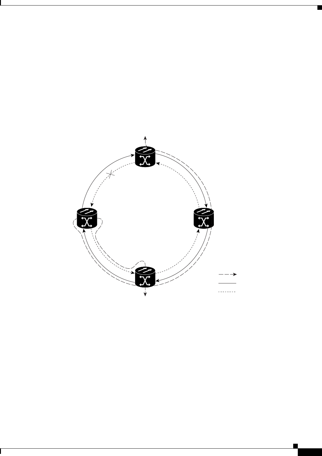
Figure 11-3 shows how traffic is rerouted after a line break between Node 0 and Node 3.
• All circuits originating on Node 0 and carried to Node 2 on Fiber 2 are switched to the protect
bandwidth of Fiber 1. For example, a circuit carried on VC4-1 on Fiber 2 is switched to VC4-9 on
Fiber 1. A circuit carried on VC4-2 on Fiber 2 is switched to VC4-10 on Fiber 1. Fiber 1 carries the
circuit to Node 3 (the original routing destination). Node 3 switches the circuit back to VC4-1 on
Fiber 2 where it is routed to Node 2 on VC4-1.
• Circuits originating on Node 2 that were normally carried to Node 0 on Fiber 1 are switched to the
protect bandwidth of Fiber 2 at Node 3. For example, a circuit carried on VC4-2 on Fiber 1 is
switched to VC4-10 on Fiber 2. Fiber 2 carries the circuit to Node 0 where the circuit is switched
back to VC4-2 on Fiber 1 and then dropped to its destination.
Figure 11-3 Four-Node, Two-Fiber MS-SPRing Traffic Pattern After Line Break
Node 0
Node 1
Node 2
Node 3
STM-16 Ring
Traffic flow
Fiber 1
Fiber 2
71277