
user manual


Table Of Contents
- Cisco ONS 15454 SDH Reference Manual
- Contents
- About this Guide
- Shelf and FMEC Hardware
- Common Control Cards
- Electrical Cards
- Optical Cards
- Ethernet Cards
- Storage Access Networking Cards
- Card Protection
- Cisco Transport Controller Operation
- Security and Timing
- Circuits and Tunnels
- SDH Topologies and Upgrades
- CTC Network Connectivity
- Alarm Monitoring and Management
- Ethernet Operation
- Hardware Specifications
- A.1 Shelf Specifications
- A.2 SFP Specifications
- A.3 General Card Specifications
- A.4 Common Control Card Specifications
- A.5 Electrical Card and FMEC Specifications
- A.5.1 E1-N-14 Card Specifications
- A.5.2 E1-42 Card Specifications
- A.5.3 E3-12 Card Specifications
- A.5.4 DS3i-N-12 Card Specifications
- A.5.5 STM1E-12 Card Specifications
- A.5.6 BLANK Card
- A.5.7 FMEC-E1 Specifications
- A.5.8 FMEC-DS1/E1 Card Specifications
- A.5.9 FMEC E1-120NP Card Specifications
- A.5.10 FMEC E1-120PROA Card Specifications
- A.5.11 FMEC E1-120PROB Card Specifications
- A.5.12 E1-75/120 Impedance Conversion Panel Specifications
- A.5.13 FMEC-E3/DS3 Card Specifications
- A.5.14 FMEC STM1E 1:1 Card Specifications
- A.5.15 FMEC-BLANK Card Specifications
- A.5.16 MIC-A/P Card Specifications
- A.5.17 MIC-C/T/P Card Specifications
- A.6 Optical Card Specifications
- A.6.1 OC3 IR 4/STM1 SH 1310 Card Specifications
- A.6.2 OC3 IR/STM1 SH 1310-8 Card Specifications
- A.6.3 OC12 IR/STM4 SH 1310 Card Specifications
- A.6.4 OC12 LR/STM4 LH 1310 Card Specifications
- A.6.5 OC12 LR/STM4 LH 1550 Card Specifications
- A.6.6 OC12 IR/STM4 SH 1310-4 Card Specifications
- A.6.7 OC48 IR/STM16 SH AS 1310 Card Specifications
- A.6.8 OC48 LR/STM16 LH AS 1550 Card Specifications
- A.6.9 OC48 ELR/STM16 EH 100 GHz Card Specifications
- A.6.10 OC192 SR/STM64 IO 1310 Card Specifications
- A.6.11 OC192 IR/STM64 SH 1550 Card Specifications
- A.6.12 OC192 LR/STM64 LH 1550 Card Specifications
- A.6.13 OC192 LR/STM64 LH ITU 15xx.xx Card Specifications
- A.7 Ethernet Card Specifications
- A.8 Storage Access Networking Card Specifications
- Administrative and Service States
- Network Element Defaults
- Index
5-6
Cisco ONS 15454 SDH Reference Manual, R5.0
April 2008
Chapter 5 Ethernet Cards
5.3.1 E1000-2-G Compatibility
Each E1000-2-G card supports standards-based, Layer 2 Ethernet switching between its Ethernet
interfaces and SDH interfaces on the ONS 15454 SDH. The IEEE 802.1Q VLAN tag logically isolates
traffic (typically subscribers).
Multiple E-Series Ethernet cards installed in an ONS 15454 SDH can act together as a single switching
entity or as independent single switches supporting a variety of SDH port configurations.
You can create logical SDH ports by provisioning a number of SDH channels to the packet switch entity
within the ONS 15454 SDH. Logical ports can be created with a bandwidth granularity of VC-4.
5.3.1 E1000-2-G Compatibility
The E1000-2-G is compatible with any traffic card slots (Slots 1 to 6 and 12 to 17).
5.3.2 E1000-2-G Card-Level Indicators
The E1000-2-G card faceplate has three card-level LED indicators (Table 5-5).
5.3.3 E1000-2-G Port-Level Indicators
The E1000-2-G card also has one bicolor LED per port (Table 5-6 ). When the LINK LED is illuminated
green, carrier is detected, meaning an active network cable is installed. When the LINK LED is not
illuminated green, an active network cable is not plugged into the port, or the card is carrying
unidirectional traffic. The port ACT LED flashes amber at a rate proportional to the level of traffic being
received and transmitted over the port.
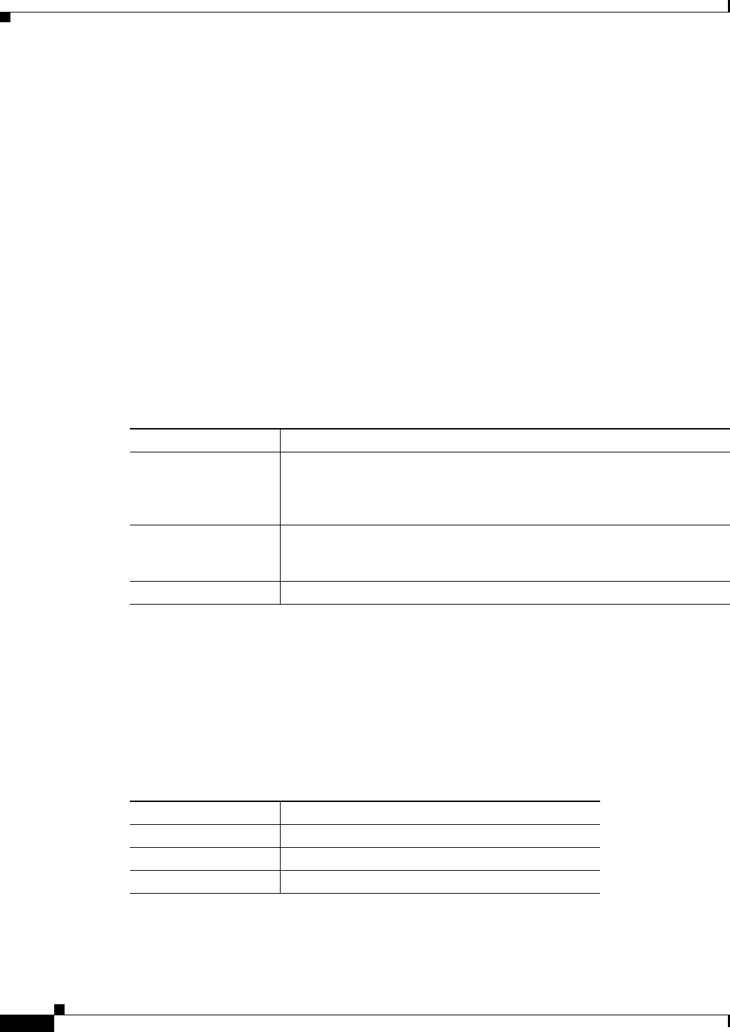
Table 5-5 E1000-2-G Card-Level Indicators
Card-Level Indicators Description
Red FAIL LED The red FAIL LED indicates that the card’s processor is not ready or that a
catastrophic software failure occurred on the E1000-2-G card. As part of the
boot sequence, the FAIL LED is turned on until the software deems the card
operational.
Green ACT LED A green ACT LED provides the operational status of the E1000-2-G. If the
ACT LED is green it indicates that the E1000-2-G card is active and the
software is operational.
SF LED Not used in this release.
Table 5-6 E1000-2-G Port-Level Indicators
LED State Description
Amber The port is active (transmitting and receiving data).
Solid green The link is established.
Green light off The connection is inactive, or traffic is unidirectional.