
user manual


Table Of Contents
- Cisco ONS 15454 SDH Reference Manual
- Contents
- About this Guide
- Shelf and FMEC Hardware
- Common Control Cards
- Electrical Cards
- Optical Cards
- Ethernet Cards
- Storage Access Networking Cards
- Card Protection
- Cisco Transport Controller Operation
- Security and Timing
- Circuits and Tunnels
- SDH Topologies and Upgrades
- CTC Network Connectivity
- Alarm Monitoring and Management
- Ethernet Operation
- Hardware Specifications
- A.1 Shelf Specifications
- A.2 SFP Specifications
- A.3 General Card Specifications
- A.4 Common Control Card Specifications
- A.5 Electrical Card and FMEC Specifications
- A.5.1 E1-N-14 Card Specifications
- A.5.2 E1-42 Card Specifications
- A.5.3 E3-12 Card Specifications
- A.5.4 DS3i-N-12 Card Specifications
- A.5.5 STM1E-12 Card Specifications
- A.5.6 BLANK Card
- A.5.7 FMEC-E1 Specifications
- A.5.8 FMEC-DS1/E1 Card Specifications
- A.5.9 FMEC E1-120NP Card Specifications
- A.5.10 FMEC E1-120PROA Card Specifications
- A.5.11 FMEC E1-120PROB Card Specifications
- A.5.12 E1-75/120 Impedance Conversion Panel Specifications
- A.5.13 FMEC-E3/DS3 Card Specifications
- A.5.14 FMEC STM1E 1:1 Card Specifications
- A.5.15 FMEC-BLANK Card Specifications
- A.5.16 MIC-A/P Card Specifications
- A.5.17 MIC-C/T/P Card Specifications
- A.6 Optical Card Specifications
- A.6.1 OC3 IR 4/STM1 SH 1310 Card Specifications
- A.6.2 OC3 IR/STM1 SH 1310-8 Card Specifications
- A.6.3 OC12 IR/STM4 SH 1310 Card Specifications
- A.6.4 OC12 LR/STM4 LH 1310 Card Specifications
- A.6.5 OC12 LR/STM4 LH 1550 Card Specifications
- A.6.6 OC12 IR/STM4 SH 1310-4 Card Specifications
- A.6.7 OC48 IR/STM16 SH AS 1310 Card Specifications
- A.6.8 OC48 LR/STM16 LH AS 1550 Card Specifications
- A.6.9 OC48 ELR/STM16 EH 100 GHz Card Specifications
- A.6.10 OC192 SR/STM64 IO 1310 Card Specifications
- A.6.11 OC192 IR/STM64 SH 1550 Card Specifications
- A.6.12 OC192 LR/STM64 LH 1550 Card Specifications
- A.6.13 OC192 LR/STM64 LH ITU 15xx.xx Card Specifications
- A.7 Ethernet Card Specifications
- A.8 Storage Access Networking Card Specifications
- Administrative and Service States
- Network Element Defaults
- Index
3-33
Cisco ONS 15454 SDH Reference Manual, R5.0
April 2008
Chapter 3 Electrical Cards
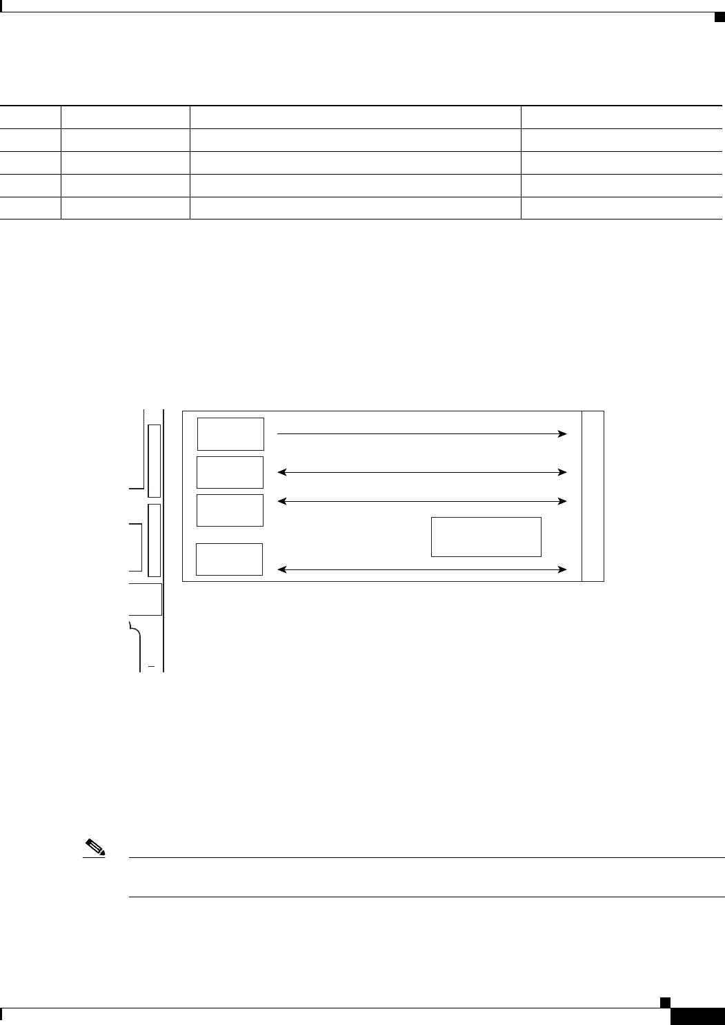
3.18 MIC-C/T/P FMEC
3.18 MIC-C/T/P FMEC
The MIC-C/T/P FMEC provides connection for the BATTERY A input, one of the two possible
redundant power supply inputs. It also provides connection for system management serial port, system
management LAN port, modem port (for future use), and system timing inputs and outputs. Install the
MIC-C/T/P in Slot 24. Figure 3-19 shows the MIC-C/T/P faceplate and block diagram.
Figure 3-19 MIC-C/T/P Faceplate and Block Diagram
The MIC-C/T/P FMEC has the following features:
• Connection for one of the two possible redundant power supply inputs
• Connection for two serial ports for local craft/modem (for future use)
• Connection for one LAN port
• Connection for two system timing inputs
• Connection for two system timing outputs
• Storage of manufacturing and inventory data
Note For proper system operation, both the MIC-A/P and the MIC-C/T/P FMECs must be installed in the
shelf.
59 VISALM2 N Normally open Critical visual alarm Black/blue
60 VISALM2 P Normally open Critical visual alarm Blue/black
61 VISALM3 N Normally open Remote visual alarm Black/orange
62 VISALM3 P Normally open Remote visual alarm Orange/black
Table 3-16 Alarm Interface Pinouts on the MIC-A/P DB-62 Connector (continued)
Pin No. Signal Name Signal Description Color
Inventory Data
(EEPROM)
134376
B
a
c
k
p
l
a
n
e
3W3
connector
Power
RJ-45
connectors
System management serial ports
RJ-45
connectors
System management LAN
4 coaxial
connectors
Timing 2 x in / 2 x out
M
ACT
LINK
CLEI CODE BARCODE
+
AUTION
E FACEPLATE
1.0 Nm TORQUE