
user manual


Table Of Contents
- Cisco Aironet 1300 Series Wireless Outdoor Access Point/Bridge Hardware Installation Guide
- Contents
- Preface
- Overview
- Installation Overview
- Mounting Overview
- Troubleshooting Autonomous Access Points and Bridges
- Checking the LEDs on an Autonomous Access Point/Bridge
- Power Injector
- Checking Power
- Checking Basic Configuration Settings
- Antenna Alignment
- Running the Carrier Busy Test
- Running the Ping or Link Test
- Resetting the Autonomous Access Point/Bridge to the Default Configuration
- Reloading the Access Point/Bridge Image
- Obtaining the Autonomous Access Point/Bridge Image File
- Connecting to the Console Serial Port
- Obtaining the TFTP Server Software
- Troubleshooting Lightweight Access Points
- Translated Safety Warnings
- Declarations of Conformity and Regulatory Information
- Manufacturers Federal Communication Commission Declaration of Conformity Statement
- VCCI Statement for Japan
- Industry Canada
- European Community, Switzerland, Norway, Iceland, and Liechtenstein
- Declaration of Conformity for RF Exposure
- Guidelines for Operating Cisco Aironet Access Points and Bridges in Japan
- Administrative Rules for Cisco Aironet Access Points and Bridges in Taiwan
- Operation of Cisco Aironet Access Points in Brazil
- Declaration of Conformity Statements
- Access Point Specifications
- Channels and Maximum Power Levels
- Console Serial Cable Pinouts
- Priming Lightweight Access Points Prior to Deployment
- Configuring DHCP Option 43 for Lightweight Access Points
- Load-Dump Protection for Transportation Vehicles
- Glossary
- Index
5-4
Cisco Aironet 1300 Series Wireless Outdoor Access Point/Bridge Hardware Installation Guide
OL-5048-06
Chapter 5 Troubleshooting Lightweight Access Points
Power Injector
Power Injector
When the power injector is powered up, it applies 48-VDC to the dual-coax cables to the access point.
When power is applied to the access point, the unit activates the bootloader and begins the POST
operations. The access point begins to load the Cisco IOS image when the POST operations are
successfully completed. Upon successfully loading the image, the unit initializes and tests the radio.
The power injector LED is shown in Figure 5-2.
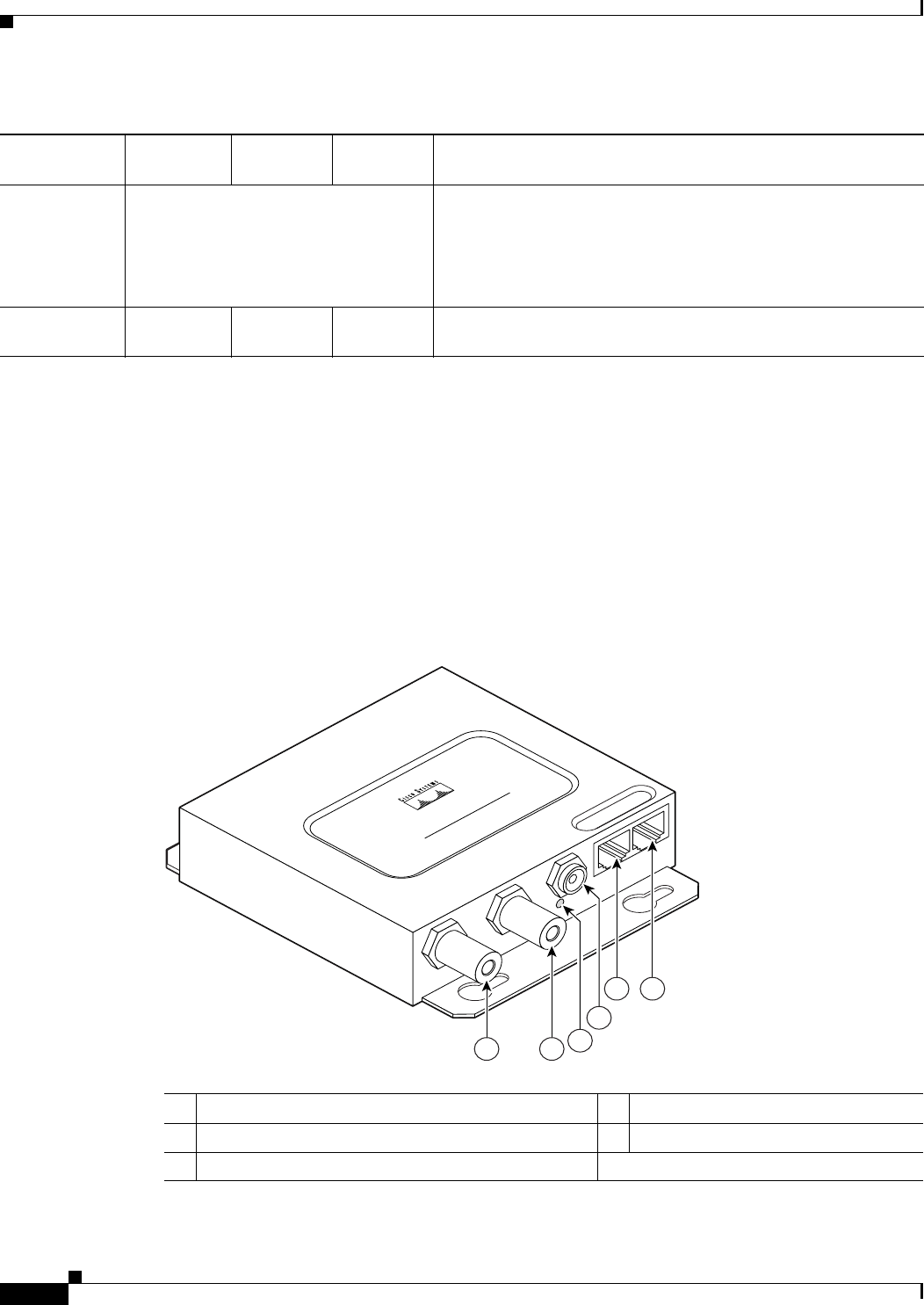
Figure 5-2 Power Injector
Controller
status
Alternating green, red, and amber
1
Connecting to the controller.
Note If the access point remains in this mode for more than five
minutes, the access point is unable to find the controller.
Ensure a DHCP server is available or that controller
information is configured on the access point.
Message
type
Ethernet
LED
Status
LED
Radio
LED Meaning
1. This status indication has the highest priority and overrides other status indications.
Table 5-1 LED Signals (continued)
Message
type
Ethernet
LED
Status
LED
Radio
LED Meaning
1 Dual-coax Ethernet ports (F-Type connectors) 4 Ethernet LAN port (RJ-45 connector)
2 Power LED 5 Console serial port (RJ-45 connector)
3 Power jack
117189
CISCO AIRONET
POWER INJECTOR
54
11
3
2