
user manual


Table Of Contents
- Cisco Aironet 1300 Series Wireless Outdoor Access Point/Bridge Hardware Installation Guide
- Contents
- Preface
- Overview
- Installation Overview
- Mounting Overview
- Troubleshooting Autonomous Access Points and Bridges
- Checking the LEDs on an Autonomous Access Point/Bridge
- Power Injector
- Checking Power
- Checking Basic Configuration Settings
- Antenna Alignment
- Running the Carrier Busy Test
- Running the Ping or Link Test
- Resetting the Autonomous Access Point/Bridge to the Default Configuration
- Reloading the Access Point/Bridge Image
- Obtaining the Autonomous Access Point/Bridge Image File
- Connecting to the Console Serial Port
- Obtaining the TFTP Server Software
- Troubleshooting Lightweight Access Points
- Translated Safety Warnings
- Declarations of Conformity and Regulatory Information
- Manufacturers Federal Communication Commission Declaration of Conformity Statement
- VCCI Statement for Japan
- Industry Canada
- European Community, Switzerland, Norway, Iceland, and Liechtenstein
- Declaration of Conformity for RF Exposure
- Guidelines for Operating Cisco Aironet Access Points and Bridges in Japan
- Administrative Rules for Cisco Aironet Access Points and Bridges in Taiwan
- Operation of Cisco Aironet Access Points in Brazil
- Declaration of Conformity Statements
- Access Point Specifications
- Channels and Maximum Power Levels
- Console Serial Cable Pinouts
- Priming Lightweight Access Points Prior to Deployment
- Configuring DHCP Option 43 for Lightweight Access Points
- Load-Dump Protection for Transportation Vehicles
- Glossary
- Index
4-14
Cisco Aironet 1300 Series Wireless Outdoor Access Point/Bridge Hardware Installation Guide
OL-5048-06
Chapter 4 Troubleshooting Autonomous Access Points and Bridges
Obtaining the Autonomous Access Point/Bridge Image File
Connecting to the Console Serial Port
If you need to configure the access point locally (without connecting to a wired LAN), you can connect
a PC to the power injector console serial port. Follow these steps to open the CLI by connecting to the
console serial port:
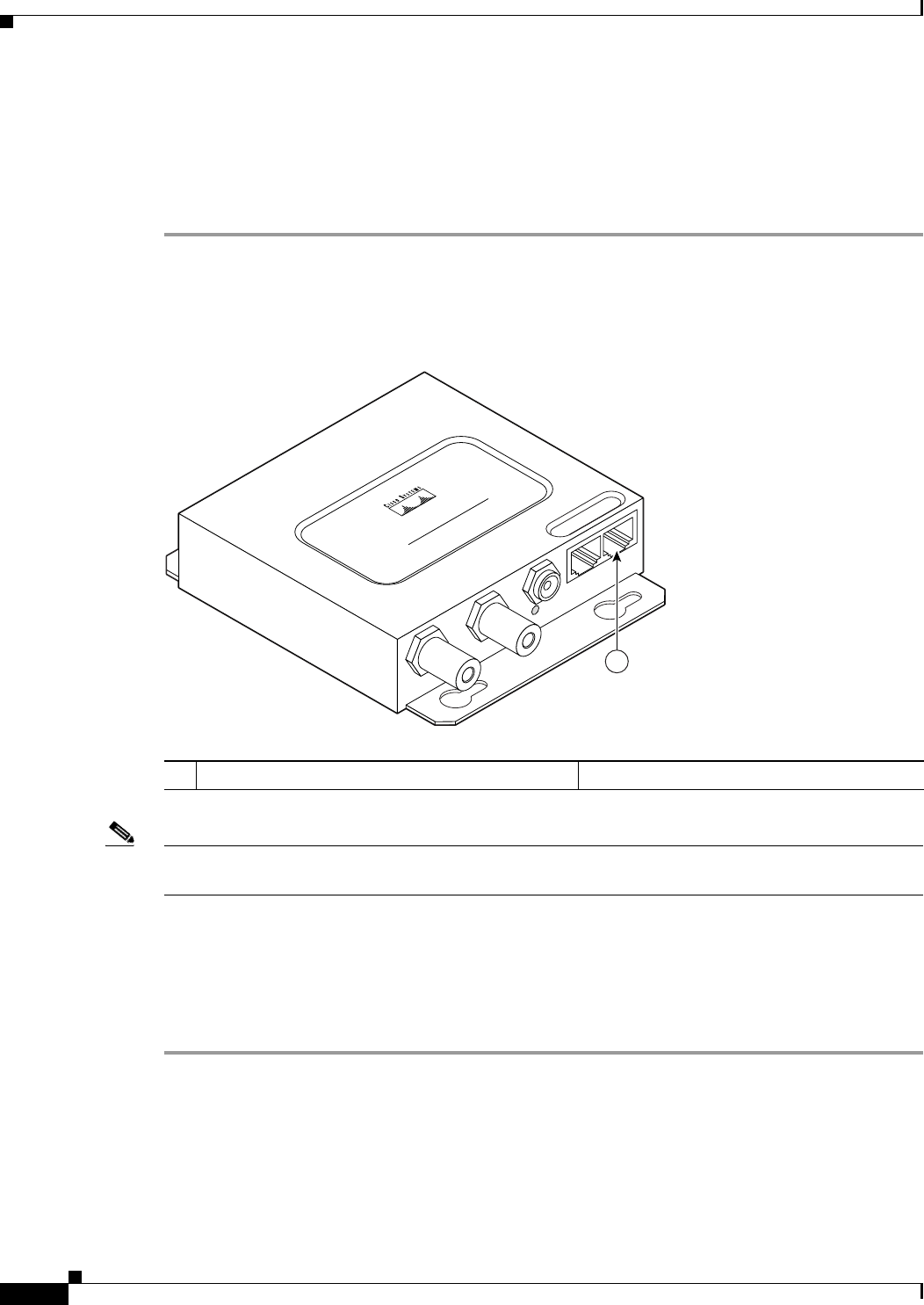
Step 1 Connect a nine-pin, female DB-9 to RJ-45 serial cable to the RJ-45 serial console port on the power
injector and to the COM port on your PC. Figure 4-3 shows the power injector’s console serial port
connector.
Figure 4-3 Console Serial Port Connector
Note The Cisco part number for the DB-9 to RJ-45 serial cable is AIR-CONCAB1200. Browse to
http://www.cisco.com/go/marketplace to order a serial cable.
Step 2 Set up a terminal emulator to communicate with the access point. Use the following settings for the
terminal emulator connection: 9600 baud, 8 data bits, no parity, 1 stop bit, and no flow control.
Step 3 When the terminal emulator is activated, press Enter.
Step 4 At the prompts, enter the administrator username and password. The default username is Cisco and the
default password is Cisco. The username and password are case sensitive.
1 Console serial port connector (RJ-45 connector)
CISCO AIRONET
POWER INJECTOR
117188
1