
user manual


Table Of Contents
- Cisco Aironet 1300 Series Wireless Outdoor Access Point/Bridge Hardware Installation Guide
- Contents
- Preface
- Overview
- Installation Overview
- Mounting Overview
- Troubleshooting Autonomous Access Points and Bridges
- Checking the LEDs on an Autonomous Access Point/Bridge
- Power Injector
- Checking Power
- Checking Basic Configuration Settings
- Antenna Alignment
- Running the Carrier Busy Test
- Running the Ping or Link Test
- Resetting the Autonomous Access Point/Bridge to the Default Configuration
- Reloading the Access Point/Bridge Image
- Obtaining the Autonomous Access Point/Bridge Image File
- Connecting to the Console Serial Port
- Obtaining the TFTP Server Software
- Troubleshooting Lightweight Access Points
- Translated Safety Warnings
- Declarations of Conformity and Regulatory Information
- Manufacturers Federal Communication Commission Declaration of Conformity Statement
- VCCI Statement for Japan
- Industry Canada
- European Community, Switzerland, Norway, Iceland, and Liechtenstein
- Declaration of Conformity for RF Exposure
- Guidelines for Operating Cisco Aironet Access Points and Bridges in Japan
- Administrative Rules for Cisco Aironet Access Points and Bridges in Taiwan
- Operation of Cisco Aironet Access Points in Brazil
- Declaration of Conformity Statements
- Access Point Specifications
- Channels and Maximum Power Levels
- Console Serial Cable Pinouts
- Priming Lightweight Access Points Prior to Deployment
- Configuring DHCP Option 43 for Lightweight Access Points
- Load-Dump Protection for Transportation Vehicles
- Glossary
- Index
4-2
Cisco Aironet 1300 Series Wireless Outdoor Access Point/Bridge Hardware Installation Guide
OL-5048-06
Chapter 4 Troubleshooting Autonomous Access Points and Bridges
Checking the LEDs on an Autonomous Access Point/Bridge
Checking the LEDs on an Autonomous Access Point/Bridge
If your autonomous access point/bridge is not associating with a remote bridge or a wireless client, check
the four LEDs on the back panel. You can use them to quickly assess the unit’s status. For information
on using the LEDs during the installation and alignment of the antenna, refer to the “LEDs” section on
page 3-5.
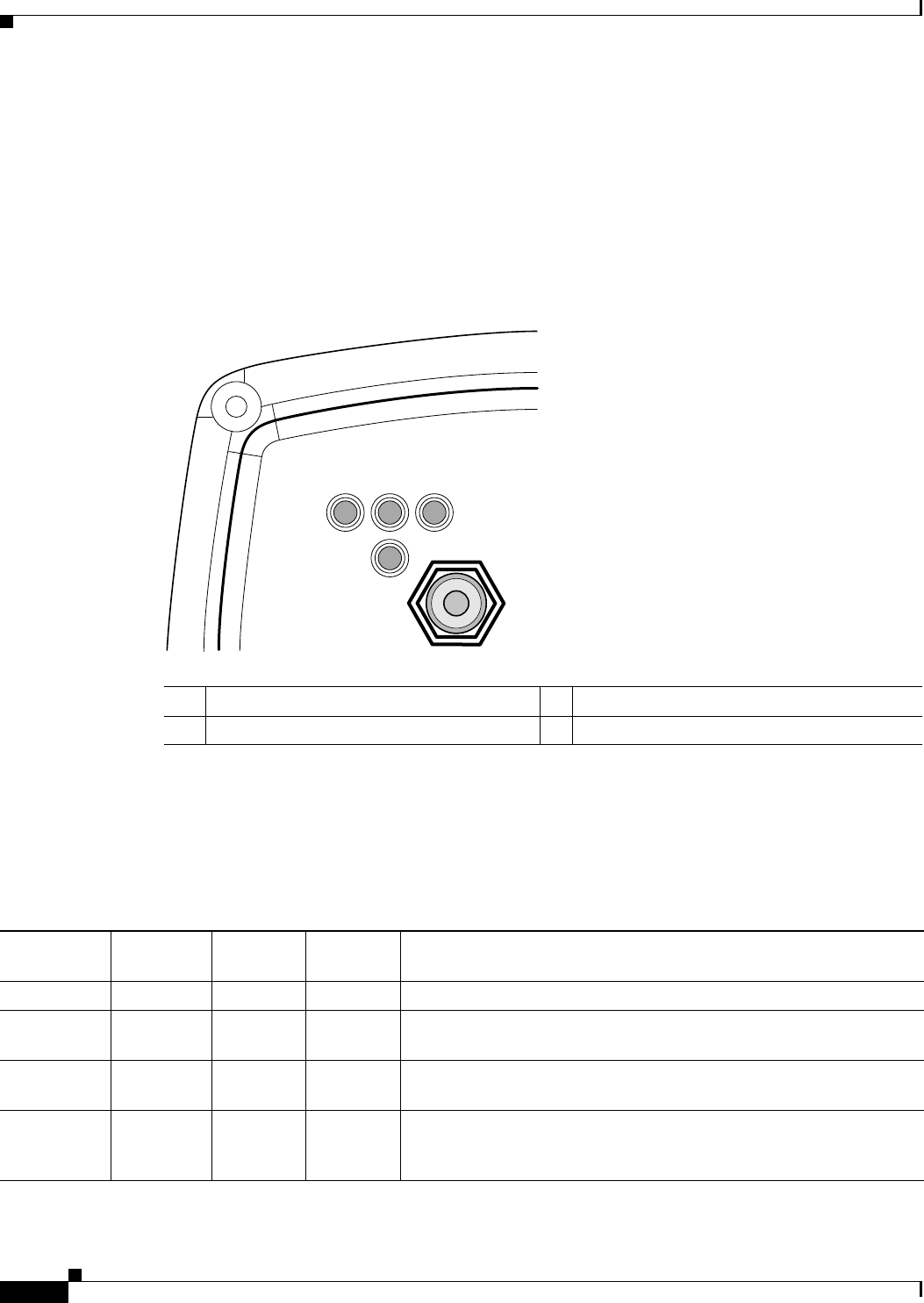
Figure 4-1 shows the access point/bridge LEDs.
Figure 4-1 LEDs
Normal Mode LED Indications for an Autonomous Access Point/Bridge
During normal operation of your autonomous access point/bridge the LEDs provide status information
as shown in Table 4-1.
R Radio LED E Ethernet LED
S Status LED I Install LED
117061
RS
I
E
Table 4-1 LED Indications
Ethernet
LED
Status
LED
Radio
LED
Install
LED
Meaning
Off — — — Ethernet link is down or disabled.
Blinking
green
— — — Transmitting and receiving Ethernet packets.
Blinking
amber
— — — Transmitting and receiving Ethernet errors.
amber — — — Firmware error—disconnect and reconnect the power injector power
jack. If the problem continues, contact technical support for
assistance.