
user manual


Table Of Contents
- Cisco Aironet 1300 Series Wireless Outdoor Access Point/Bridge Hardware Installation Guide
- Contents
- Preface
- Overview
- Installation Overview
- Mounting Overview
- Troubleshooting Autonomous Access Points and Bridges
- Checking the LEDs on an Autonomous Access Point/Bridge
- Power Injector
- Checking Power
- Checking Basic Configuration Settings
- Antenna Alignment
- Running the Carrier Busy Test
- Running the Ping or Link Test
- Resetting the Autonomous Access Point/Bridge to the Default Configuration
- Reloading the Access Point/Bridge Image
- Obtaining the Autonomous Access Point/Bridge Image File
- Connecting to the Console Serial Port
- Obtaining the TFTP Server Software
- Troubleshooting Lightweight Access Points
- Translated Safety Warnings
- Declarations of Conformity and Regulatory Information
- Manufacturers Federal Communication Commission Declaration of Conformity Statement
- VCCI Statement for Japan
- Industry Canada
- European Community, Switzerland, Norway, Iceland, and Liechtenstein
- Declaration of Conformity for RF Exposure
- Guidelines for Operating Cisco Aironet Access Points and Bridges in Japan
- Administrative Rules for Cisco Aironet Access Points and Bridges in Taiwan
- Operation of Cisco Aironet Access Points in Brazil
- Declaration of Conformity Statements
- Access Point Specifications
- Channels and Maximum Power Levels
- Console Serial Cable Pinouts
- Priming Lightweight Access Points Prior to Deployment
- Configuring DHCP Option 43 for Lightweight Access Points
- Load-Dump Protection for Transportation Vehicles
- Glossary
- Index
3-5
Cisco Aironet 1300 Series Wireless Outdoor Access Point/Bridge Hardware Installation Guide
OL-5048-06
Chapter 3 Mounting Overview
LEDs
LEDs
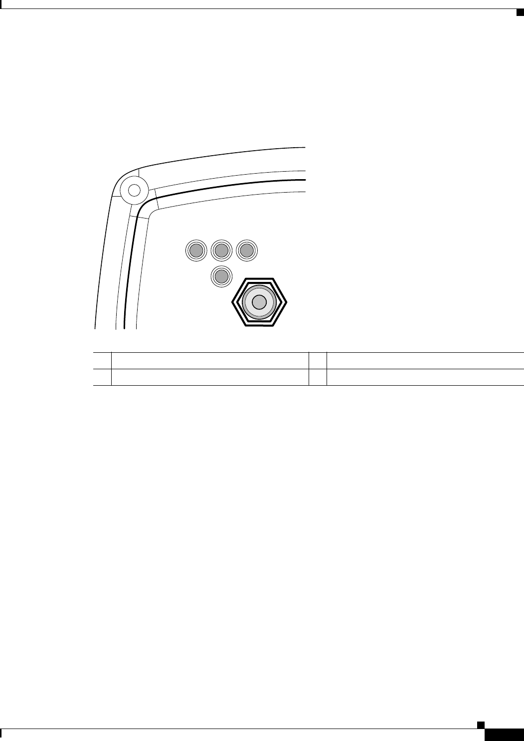
The LEDs indicate the status, radio activity, and Ethernet activity. The LEDs are mounted on the back
of the housing (see Figure 3-2).
Figure 3-2 LEDs
For additional information on LED indications, refer to the “Troubleshooting Autonomous Access
Points and Bridges” section on page 4-1 or the “Troubleshooting Lightweight Access Points” section on
page 5-1.
Autonomous Access Point/Bridge
When the autonomous access point/bridge running Cisco IOS Release 12.3(4)JA is initially powered-up,
the unit defaults to a root access point with the radio disabled and no default SSID. To allow client
associations, you must configure an SSID and enable the radio interface (refer to the Cisco IOS Software
Configuration Guide for Access Points).
When the autonomous access point/bridge running Cisco IOS Release 12.3(2)JA2 and earlier is initially
powered-up, the bridge installation mode is activated and the unit attempts to associate to a root bridge
for 60 seconds. If it is unable to associate with a root bridge, it automatically assumes the root bridge
role.
R Radio LED E Ethernet LED
S Status LED I Install LED
117061
RS
I
E