
user manual


Table Of Contents
- Cisco Aironet 1300 Series Wireless Outdoor Access Point/Bridge Hardware Installation Guide
- Contents
- Preface
- Overview
- Installation Overview
- Mounting Overview
- Troubleshooting Autonomous Access Points and Bridges
- Checking the LEDs on an Autonomous Access Point/Bridge
- Power Injector
- Checking Power
- Checking Basic Configuration Settings
- Antenna Alignment
- Running the Carrier Busy Test
- Running the Ping or Link Test
- Resetting the Autonomous Access Point/Bridge to the Default Configuration
- Reloading the Access Point/Bridge Image
- Obtaining the Autonomous Access Point/Bridge Image File
- Connecting to the Console Serial Port
- Obtaining the TFTP Server Software
- Troubleshooting Lightweight Access Points
- Translated Safety Warnings
- Declarations of Conformity and Regulatory Information
- Manufacturers Federal Communication Commission Declaration of Conformity Statement
- VCCI Statement for Japan
- Industry Canada
- European Community, Switzerland, Norway, Iceland, and Liechtenstein
- Declaration of Conformity for RF Exposure
- Guidelines for Operating Cisco Aironet Access Points and Bridges in Japan
- Administrative Rules for Cisco Aironet Access Points and Bridges in Taiwan
- Operation of Cisco Aironet Access Points in Brazil
- Declaration of Conformity Statements
- Access Point Specifications
- Channels and Maximum Power Levels
- Console Serial Cable Pinouts
- Priming Lightweight Access Points Prior to Deployment
- Configuring DHCP Option 43 for Lightweight Access Points
- Load-Dump Protection for Transportation Vehicles
- Glossary
- Index
2-5
Cisco Aironet 1300 Series Wireless Outdoor Access Point/Bridge Hardware Installation Guide
OL-5048-06
Chapter 2 Installation Overview
Installation Guidelines
Typical Outdoor Installation Components
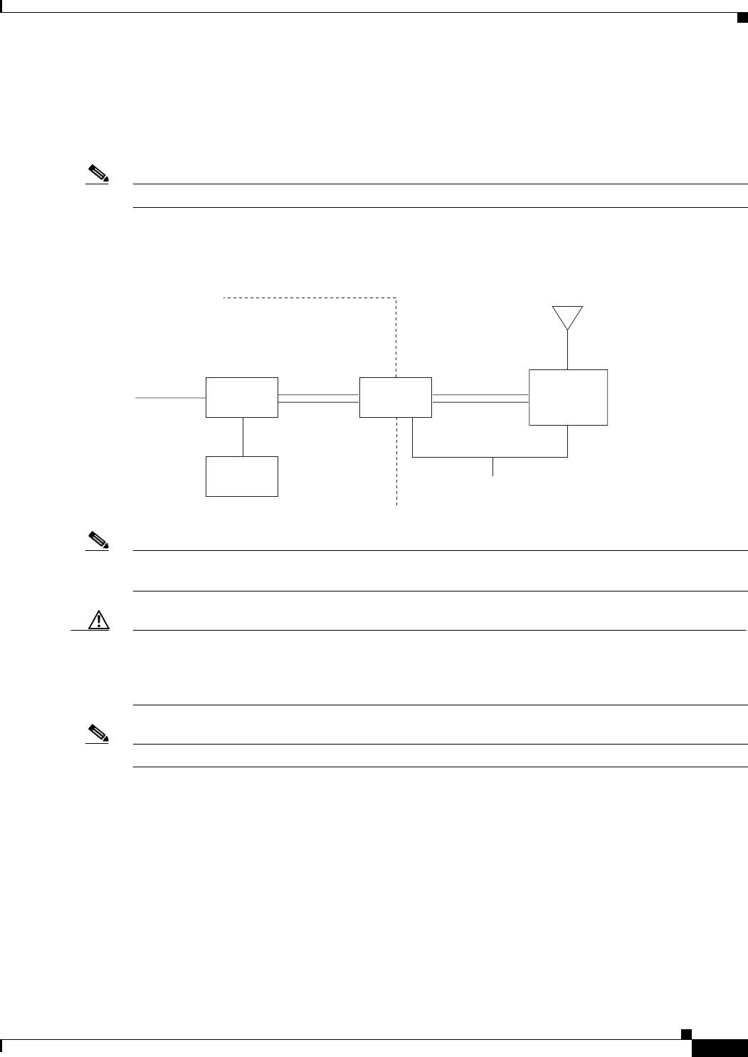
The access point/bridge is designed to be installed in an outdoor environment, typically on a tower or a
tall building. A typical outdoor installation diagram is shown in Figure 2-1.
Note The lightweight access point can only operate as an access point.
Figure 2-1 Typical Outdoor Installation Diagram
Note Ground wires must comply with Sections 810 and 820 of the National Electrical Code and Section 54 of
the Canadian Electrical Code.
Caution To ensure correct installation and grounding, install the access point/bridge in compliance with your
local and national electrical codes: National Fire Protection Association (NFPA) 70, National Electrical
Code (U.S.); Canadian Electrical Code, Part I, CSA 22.1 (Canada); and if local or national electrical
codes are not available, refer to IEC 364, Part 1 through 7 (other countries).
Note The grounding block is not required for indoor installations of the access point/bridge and antenna.
Installation Guidelines
Because the access point/bridge is a radio device, it is susceptible to common causes of interference that
can reduce throughput and range. Follow these basic guidelines to ensure the best possible performance:
• Install the access point/bridge in an area where structures, trees, or hills do not obstruct radio signals
to and from the unit.
• Install the access point/bridge at a height sufficient to provide a clear line-of-sight signal path.
155881
Category 5
Ethernet
cable
Dual-coax
cables
Dual-coax
cables
Indoor
Building
entrance
Outdoor
Ground
(see note)
Power
injector
Power
module
Grounding
block
BR1310G or
LAP1310G
Integrated
or
external antenna