
user manual
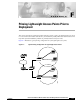


Table Of Contents
- Cisco Aironet 1300 Series Wireless Outdoor Access Point/Bridge Hardware Installation Guide
- Contents
- Preface
- Overview
- Installation Overview
- Mounting Overview
- Troubleshooting Autonomous Access Points and Bridges
- Checking the LEDs on an Autonomous Access Point/Bridge
- Power Injector
- Checking Power
- Checking Basic Configuration Settings
- Antenna Alignment
- Running the Carrier Busy Test
- Running the Ping or Link Test
- Resetting the Autonomous Access Point/Bridge to the Default Configuration
- Reloading the Access Point/Bridge Image
- Obtaining the Autonomous Access Point/Bridge Image File
- Connecting to the Console Serial Port
- Obtaining the TFTP Server Software
- Troubleshooting Lightweight Access Points
- Translated Safety Warnings
- Declarations of Conformity and Regulatory Information
- Manufacturers Federal Communication Commission Declaration of Conformity Statement
- VCCI Statement for Japan
- Industry Canada
- European Community, Switzerland, Norway, Iceland, and Liechtenstein
- Declaration of Conformity for RF Exposure
- Guidelines for Operating Cisco Aironet Access Points and Bridges in Japan
- Administrative Rules for Cisco Aironet Access Points and Bridges in Taiwan
- Operation of Cisco Aironet Access Points in Brazil
- Declaration of Conformity Statements
- Access Point Specifications
- Channels and Maximum Power Levels
- Console Serial Cable Pinouts
- Priming Lightweight Access Points Prior to Deployment
- Configuring DHCP Option 43 for Lightweight Access Points
- Load-Dump Protection for Transportation Vehicles
- Glossary
- Index

F-3
Cisco Aironet 1300 Series Wireless Outdoor Access Point/Bridge Hardware Installation Guide
OL-5048-06
Appendix F Priming Lightweight Access Points Prior to Deployment
Step 6 If the operating system download is successful, the access point reboots. Normal operation is indicated
when the radio LED is blinking to indicate radio activity.
Step 7 Use the controller CLI, controller GUI, or Cisco WCS to configure the access point with primary,
secondary, and tertiary controller names.
Step 8 If the access point is in a Controller Mobility Group, use the controller CLI, controller GUI, or Cisco
WCS to configure the Controller Mobility Group name.
Step 9 Use the controller CLI, controller GUI, or Cisco WCS to configure the access point-specific 802.11a,
802.11b and 802.11g network settings.
Step 10 If the configuration priming was successful, the radio LED is blinking to indicate normal operation.
Step 11 Repeat Steps 4 to 9 for each access point.
When you successfully complete the configuration priming of all your access points, ensure the Master
setting is disabled on your controller. Also you can begin deploying the access points to their final
destinations.