Doc. No. 78-4337-02 Cisco 12012 Gigabit Switch Router Card Cage Assembly Replacement Instructions Product Number: GSR12-CARDCAGE= This document contains instructions for removing and replacing a card cage assembly in the Cisco 12012 Gigabit Switch Router (GSR).
Product Overview Figure 1 Cisco 12012—Front View Top blower module (behind front cover) Frame 0 CT EJE R IVE RIE PKT ACT CAR RX T-1 SLO T-0 SLO 1 0 0 X AU ET RES CRI R L IVE RIE CEL ACT CAR RX R L IVE RIE CEL ACT CAR RX AL OR OR TIC MAJ MIN R IVE RIE PKT ACT CAR RX 2 E SOL CON /LT ACO R IVE RIE PKT ACT CAR RX ALARM 1 3 TX L COL RX R IVE RIE PKT ACT CAR RX LINK Upper card cage MII ALARM 2 5 RJ-4 ENA FAIL D BLE 0 OC-12/STM-4 POS 1 CSC 0 1 2 ALARM SFC Q OC-3/STM-POS OC-
Safety Guidelines Safety Guidelines Before you begin the replacement procedure, review the safety guidelines in this section to avoid injuring yourself or damaging the equipment. This section also repeats in multiple languages the warnings in this document.
Safety Guidelines Warnung Dieses Warnsymbol bedeutet Gefahr. Sie befinden sich in einer Situation, die zu einer Körperverletzung führen könnte. Bevor Sie mit der Arbeit an irgendeinem Gerät beginnen, seien Sie sich der mit elektrischen Stromkreisen verbundenen Gefahren und der Standardpraktiken zur Vermeidung von Unfällen bewußt.
Safety Guidelines Safety with Electricity The line cards, RP, switch fabric cards, blower modules, and redundant power supplies are designed to be removed and replaced while the system is operating without presenting an electrical hazard or damage to the system. Follow these basic guidelines when working with any electrical equipment: • Before beginning any procedures requiring access to the interior of the Cisco 12012, locate the emergency power-off switch for the room in which you are working.
Tools and Parts Required Preventing Electrostatic Discharge Damage Electrostatic discharge damage, which can occur when electronic boards or components are handled improperly, can result in complete or intermittent failures. Following are guidelines for preventing ESD damage: • Always use an ESD-preventive wrist strap or ankle strap and ensure that it makes good skin contact.
Removing and Replacing a Card Cage Assembly Removing and Replacing a Card Cage Assembly This section covers removing and replacing of the card cage assembly. The card cage assembly comprises a single assembly that includes the upper card cage, the lower card cage, and the power supply bays. The assembly slides into and out of the frame and attaches to the frame with six captive screws. An empty card cage assembly weighs 65 lb (29.5 kg).
Removing and Replacing a Card Cage Assembly Removing an AC-Input Power Supply Perform the following steps to remove an AC-input power supply: Step 1 Attach an antistatic wrist strap to yourself and to one of the two ESD connection sockets located on the front edges of the upper card cage or to bare metal on the frame. Step 2 If you have not already done so, turn the power supply power switch to the STANDBY position on the power supply you want to remove. (Refer to Figure 2a.
Removing and Replacing a Card Cage Assembly Step 7 Figure 3 Grasp the power supply handle and pull straight out to disconnect the power supply from the backplane connector. Slide the power supply halfway out of the bay slot. (Refer to Figure 3.
Removing and Replacing a Card Cage Assembly Removing a DC-Input Power Supply Perform the following steps to remove a DC-input power supply: Caution Before performing any of the following procedure, ensure that power is removed from the DC circuit. To ensure that all power is OFF, locate the circuit breaker on the panel board that services the DC circuit, switch the circuit breaker to the OFF position, and tape the switch handle of the circuit breaker in the OFF position.
Removing and Replacing a Card Cage Assembly Figure 4 Removing a DC-Input Power Supply H10600 DC-input power supply Use two hands to slide power supply out of bay Caution The DC-input power supply weighs 19 lb (8.3 kg). Use two hands when handling the power supply. Step 6 Place your free hand underneath the power supply for support and slide the power supply completely out of the bay. Set the power supply aside Repeat Step 2 through Step 6 for the rest of the DC-input power supplies.
Removing and Replacing a Card Cage Assembly Removing the Cards From the Upper Card Cage This section provides the procedures for removing the line cards, RP, and alarm card from the upper card cage. Note You must remove any blank cards installed in the upper card cage and retain them for use in the replacement card cage. Blank cards must be installed in slots without cards to maintain proper air flow and for EMI considerations.
Removing and Replacing a Card Cage Assembly Step 3 Proceeding from left to right in the upper card cage, select a line card. Starting with the bottom port on the line card, disconnect the network interface cable from the bottom port on the line card. (Refer to Figure 5a.) Step 4 Carefully remove the interface cable from the vertical cable-management bracket clips. (Refer to Figure 5b.
Removing and Replacing a Card Cage Assembly Step 7 Proceeding from left to right in the upper card cage, select a line card and loosen the two captive screws located at the top and bottom of the line card (Refer to Figure 6a.) Step 8 Pivot the two card ejector levers out, away from the card to unseat the card from the backplane connector. (Refer to Figure 6b.) Step 9 Grasp the card carrier edge with one hand and place your other hand under the carrier to support it. (Refer to Figure 6c.
Removing and Replacing a Card Cage Assembly Step 3 Loosen the two captive screws at the top and bottom of the RP. (Refer to Figure 7a.) Step 4 Pivot the two ejector levers out, away from the card, to unseat the card from the backplane connector. (Refer to Figure 7b.) Step 5 Grasp the card carrier edge with one hand and place your other hand under the carrier to support it. (Refer to Figure 7c.) Slide the card out of the slot and place it immediately on the antistatic mat.
Removing and Replacing a Card Cage Assembly Step 3 Loosen the two captive screws at the top and bottom of the alarm card. (Refer to Figure 8a.) Note Unlike the line cards and RP, the alarm card does not have card ejector levers. The alarm card backplane connector is smaller, has fewer pins, and is easier to seat and unseat than the line cards and the RP. Step 4 Using a flat-blade screwdriver, gently pry at the top and bottom of the alarm card carrier to unseat the card from the backplane connector.
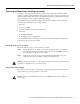
Removing and Replacing a Card Cage Assembly Step 2 To gain access to the lower card cage, loosen the two captive screws at the top of the air filter tray and pivot the tray down, away from the lower card cage. (Refer to Figure 9.
Removing and Replacing a Card Cage Assembly Figure 10 To access the cards in the lower card cage, you must first move the air deflector up, out of the way. Lift the air deflector up and secure it to the top of the lower card cage by turning the air deflector latch knob counterclockwise. (Refer to Figure 10.
Removing and Replacing a Card Cage Assembly Select one of the cards in the lower card cage to remove. Grasp the two card ejector levers and simultaneously pivot both ejector levers ninety degrees inward (away from the sides of the card cage) to unseat the card from the backplane connector. (Refer to Figure 11.
Removing and Replacing a Card Cage Assembly Removing the System Grounding Your system might have two system grounding cable lugs attached to two system receptacles located on the card cage assembly side flanges between the air filter tray and the power supply bays. (Refer to Figure 12.) You must remove the system grounding connector before you can remove card cage assembly.
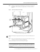
Removing and Replacing a Card Cage Assembly Figure 13 Removing a System Grounding Cable Bolts System grounding receptacles H10898 Grounding lug Removing the Card Cage Assembly Perform the following steps to remove the card cage assembly (refer to Figure 14): Caution An empty card cage assembly weighs 65 lb (29.5 kg). You need two people to safely lift the assembly. To prevent injury, keep your back straight and lift with your legs, not your back.
Removing and Replacing a Card Cage Assembly Figure 14 Removing the Card Cage Assembly From the Frame Front handle (2 places) Frame Card cage assembly Handhold cutout 22 Cisco 12012 Gigabit Switch Router Card Cage Assembly Replacement Instructions H10475 Captive screw (6 places)
Removing and Replacing a Card Cage Assembly Installing a New Card Cage Assembly The new card cage assembly is shipped with a new air filter installed in the air filter tray. You must replace the components you removed from the old card cage assembly in the new card cage assembly. Caution An empty card cage assembly weighs 65 lb (29.5 kg). You need two people to safely lift the assembly. To prevent injury, keep your back straight and lift with your legs, not your back.
Removing and Replacing a Card Cage Assembly Step 4 Grasp the card carrier edge with one hand and place your other hand under the carrier to support and guide it into a matching color-coded slot. Slide the card halfway into the lower card cage slot. Avoid touching the card circuitry or any connectors.
Removing and Replacing a Card Cage Assembly Step 4 Grasp the two line card ejector levers and pivot them away from the card until they are perpendicular to the line card faceplate to completely seat the card in the backplane connector. Step 5 Tighten the two captive screws at the top and bottom of the line card. Repeat Step 2 through Step 5 for the rest of the line cards.
Removing and Replacing a Card Cage Assembly Step 8 Proceeding from bottom port to the top port (line cards with multiple ports only) identify the interface cable that connects to each line card port. Connect the interface cable to the line card port. (Refer to Figure 15a.) Step 9 Proceeding from bottom port to the top port (line cards with multiple ports only), carefully press the interface cable into the vertical cable bracket cable clip. (Refer to Figure 15b.
Removing and Replacing a Card Cage Assembly Note Adjust the interface cable in the vertical cable bracket cable clips to prevent any kinks or sharp bends in the interface cable. Allow adequate strain relief in the interface cable. Repeat Step 6 through Step 10 for the rest of the interface cables and line cards. Note Blank cards must be installed in the upper card cage to fill any open slots. The blank cards are used to maintain proper air flow and for EMI considerations.
Removing and Replacing a Card Cage Assembly Installing the System Grounding Your system might have two system grounding cable lugs. The system grounding receptacles are located on the card cage assembly side flanges between the air filter tray and the power supply bay. (Refer to Figure 12.) Perform the following steps to install the system grounding lugs to the card cage assembly: Step 1 Position the system ground lug over the card cage assembly system grounding receptacle.
Removing and Replacing a Card Cage Assembly Step 3 Using two hands to support and guide the power supply, slide it into the vacant power supply bay position. Push the power supply all the way into the power supply bay until the faceplate makes contact with the front of the bay. Note All electrical connections between the power supply and the backplane are made automatically when the power supply is fully inserted in the power supply bay. Step 4 Tighten the captive screw on the power supply faceplate.
Removing and Replacing a Card Cage Assembly Step 3 Figure 16 Using two hands to support and guide the power supply, carefully slide it into the vacant bay. (Refer to Figure 16.) Stop when the power supply captive jackscrew makes contact with the front of the power supply bay.
Removing and Replacing a Card Cage Assembly Note The captive jackscrew is used to align and draw the power supply connector into the backplane connector. To prevent connector alignment problems, apply even pressure on the power supply handle as you turn the captive jackscrew. Step 4 Keep one hand on the power supply handle and apply even pressure to the power supply as you turn the captive jackscrew clockwise (insert) using a 10-mm nutdriver or flat-blade screwdriver. Do not overtighten the jackscrew.
FCC Class A Compliance Step 3 Verify that all source voltage circuit breakers supplying power to your system are on. Step 4 Turn the power switch on each power supply to ON (|). The input OK LED on each DC-input power supply (AC OK LED on each AC-input power supply) should go on. Note Turning the power supply switch to ON (|) also engages a latch securing the power supply in place. Step 5 Listen for the blower modules to power up.
Cisco Connection Online Cisco Connection Online Cisco Connection Online (CCO) is Cisco Systems’ primary, real-time support channel. Maintenance customers and partners can self-register on CCO to obtain additional information and services. Available 24 hours a day, 7 days a week, CCO provides a wealth of standard and value-added services to Cisco’s customers and business partners.
Cisco Connection Online 34 Cisco 12012 Gigabit Switch Router Card Cage Assembly Replacement Instructions