Cisco 2800 Series Hardware Documents: Introduction and Warnings This introduction discusses the objectives, audience, organization, and conventions of these hardware documents, and points to related documents that have information beyond the scope of these documents.
Audience These documents describe several router platforms that are similar in functionality, but differ in the number of interfaces supported. Some information provided may not apply to your particular router model. To access warranty, service, and support information, see the “Cisco 90-Day Limited Hardware Warranty Terms” section on page 10.
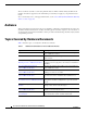
Conventions Table 1 Hardware Documentation for Cisco 2800 Series Routers (Continued) Topic Description Installing and Upgrading Internal Modules in Cisco 2800 Series Routers Describes how to install or upgrade modules that are located internally within the router, such as memory modules, AIMs, PVDMs, and power supplies. Removing and Installing CompactFlash Memory Cards in Cisco 2800 Series Routers Describes hardware installation procedures that do not require opening the chassis.
Safety Warnings Safety Warnings Safety warnings appear throughout these publications in procedures that, if performed incorrectly, may harm you. A warning symbol precedes each warning statement. To see translations of the warnings that appear in these publications, refer to the Cisco 2800 Series Routers Regulatory Compliance and Safety Information document that accompanied your router. Warning Definition Warning IMPORTANT SAFETY INSTRUCTIONS This warning symbol means danger.
Safety Warnings Warnung WICHTIGE SICHERHEITSANWEISUNGEN Dieses Warnsymbol bedeutet Gefahr. Sie befinden sich in einer Situation, die zu einer Körperverletzung führen könnte. Bevor Sie mit der Arbeit an irgendeinem Gerät beginnen, seien Sie sich der mit elektrischen Stromkreisen verbundenen Gefahren und der Standardpraktiken zur Vermeidung von Unfällen bewusst. Übersetzungen der in dieser Veröffentlichung enthaltenen Warnhinweise sind im Lieferumfang des Geräts enthalten.
Safety Warnings Varning! VIKTIGA SÄKERHETSANVISNINGAR Denna varningssignal signalerar fara. Du befinner dig i en situation som kan leda till personskada. Innan du utför arbete på någon utrustning måste du vara medveten om farorna med elkretsar och känna till vanliga förfaranden för att förebygga olyckor. Se översättningarna av de varningsmeddelanden som finns i denna publikation, och se de översatta säkerhetsvarningarna som medföljer denna anordning.
Safety Warnings Aviso INSTRUÇÕES IMPORTANTES DE SEGURANÇA Este símbolo de aviso significa perigo. Você se encontra em uma situação em que há risco de lesões corporais. Antes de trabalhar com qualquer equipamento, esteja ciente dos riscos que envolvem os circuitos elétricos e familiarize-se com as práticas padrão de prevenção de acidentes. Use o número da declaração fornecido ao final de cada aviso para localizar sua tradução nos avisos de segurança traduzidos que acompanham o dispositivo.
Safety Warnings Cisco 2800 Series Hardware Documents: Introduction and Warnings 8 OL-5808-01
Related Documentation Related Documentation The Cisco IOS software running your Cisco 2800 series router includes extensive features and functionality. For information that is beyond the scope of these documents, or for additional information, use the following resources: Timesaver Make sure that you have access to the documents listed in Table 3. Some of these documents are available in print, and all are on the World Wide Web.
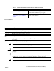
Cisco 90-Day Limited Hardware Warranty Terms Table 3 Related and Referenced Documents Cisco Product Document Title Cisco 2800 series routers Cisco 2800 Series Routers Quick Start Guide Software configuration documentation for Cisco 2800 series routers Cisco 2800 Series and Cisco 3800 Series Routers Regulatory Compliance and Safety Information Cisco 2800 Series Cards and Modules Cisco Modular Access Router Cable Specifications Cisco RPS-675 Redundant Power System Hardware Installation Guide Quick Start
Obtaining Documentation Note 3. You must have Adobe Acrobat Reader to view and print PDF files. You can download the reader from Adobe’s website: http://www.adobe.com To read translated and localized warranty information about your product, follow these steps: a. Enter this part number in the Warranty Document Number field: 78-5236-01C0 b. Select the language in which you would like to read the document. c. Click Go. The Cisco warranty page appears. d.
Documentation Feedback Cisco.com You can access the most current Cisco documentation at this URL: http://www.cisco.com/univercd/home/home.htm You can access the Cisco website at this URL: http://www.cisco.com You can access international Cisco websites at this URL: http://www.cisco.com/public/countries_languages.shtml Ordering Documentation You can find instructions for ordering documentation at this URL: http://www.cisco.com/univercd/cc/td/doc/es_inpck/pdi.
Obtaining Technical Assistance Cisco Technical Support Website The Cisco Technical Support Website provides online documents and tools for troubleshooting and resolving technical issues with Cisco products and technologies. The website is available 24 hours a day, 365 days a year at this URL: http://www.cisco.com/techsupport Access to all tools on the Cisco Technical Support Website requires a Cisco.com user ID and password.
Obtaining Additional Publications and Information Obtaining Additional Publications and Information Information about Cisco products, technologies, and network solutions is available from various online and printed sources. • Cisco Marketplace provides a variety of Cisco books, reference guides, and logo merchandise. Visit Cisco Marketplace, the company store, at this URL: http://www.cisco.
Obtaining Additional Publications and Information Cisco 2800 Series Hardware Documents: Introduction and Warnings OL-5808-01 15
Obtaining Additional Publications and Information CCVP, the Cisco Logo, and the Cisco Square Bridge logo are trademarks of Cisco Systems, Inc.; Changing the Way We Work, Live, Play, and Learn is a service mark of Cisco Systems, Inc.
Overview of Cisco 2800 Series Routers The Cisco 2800 series of integrated services routers offers secure, wire-speed delivery of concurrent data, voice, and video services. The modular design of the Cisco 2800 series routers provides maximum flexibility, allowing you to configure your router to meet evolving needs. The Cisco 2800 series routers incorporate data, security, and voice services in a single system for fast, scalable delivery of crucial business applications.
Hardware Features Figure 2 SYS AUX PWR PWR/ SYS ACT Front View of a Cisco 2811 Router CF COMPACT Do Not Rem ove Durin CONSOL 1 FLASH g Network E OPTIONA L RPS INPU T 0 AUX Operation 12V -48V 11A 4A 95902 100-240 V~ 4A 50/60 Hz Figure 3 Front View of a Cisco 2821 or Cisco 2851 Router SYS AUX PWR PWR/ SYS ACT CF COMPACT OPTIONAL RPS 12V -48V INPUT Do Not Rem ove Durin CONSOL 1 FLASH g Network E 0 AUX Operation 11A 4A 95903 100-240 V~ 4A 50/60 Hz This chapter describes th
Hardware Features Serial Number Location on the Cisco 2801 Router 117342 781-00286-01 Figure 4 SN: AAANNN NXXXX SN: AAANNNNXXXX Note The serial number for Cisco 2801 routers is 11 characters long. The serial number label for Cisco 2811 routers is located on the rear of the chassis, near the top right corner, to the left of the CLEI label. (See Figure 5.
Hardware Features The serial number label for Cisco 2821 and Cisco 2851 routers is located on the rear of the chassis, near the top right corner, below the CLEI label. (See Figure 6.) Figure 6 A= ACT S= SPEED FE 0/1 A F Serial Number Location on the Cisco 2821 and Cisco 2851 Routers A= FDX A= LINK FE 0/0 A S F L S PVDM2 L PVDM1 PVDM0 AIM1 AIM0 103963 781-00288-01 SN: AAANNN NXXXX SN: AAANNNNXXXX Note The serial number for Cisco 2821 and Cisco 2851 routers is 11 characters long.
Hardware Features Removable and Interchangeable Modules Table 2 summarizes the optional modules that can be installed in the router to provide specific capabilities. The network modules, extension voice modules, and interface cards fit into slots, located on the front of the chassis on the Cisco 2801 router, and on the rear of the chassis on the Cisco 2811, Cisco 2821, and Cisco 2851 routers; they can be removed and installed without opening the chassis.
Hardware Features Memory Cisco 2800 series routers contain the following types of memory: • DRAM—Stores the running configuration and routing tables and is used for packet buffering by the network interfaces. Cisco IOS software executes from DRAM memory. • Boot/NVRAM—Internal flash memory. Stores the bootstrap program (ROM monitor), the configuration register, and the startup configuration. • Flash memory—External flash memory. Stores the operating system software image.
Hardware Features Power Table 4 summarizes the power options for Cisco 2800 series routers. Cisco 2801 routers are equipped for operation using AC power only. Cisco 2811, Cisco 2821, and Cisco 2851 routers can be equipped for operation using either AC or DC input power by installation of the appropriate chassis power supply. IP phone power is supported if the appropriate AC-input chassis power supply is installed.
Hardware Features To see descriptions of LEDs in removable modules and interface cards, refer to the applicable documentation for those products: the Cisco Network Modules Hardware Installation Guide or the Cisco Interface Cards Installation Guide. For LED troubleshooting information, including possible trouble causes and corrective actions, see Table 1 in the “Troubleshooting Cisco 2800 Series Routers” document.
Hardware Features Table 6 Summary of Cisco 2811, Cisco 2821, and Cisco 2851 Series LED Indicators LED Location Front of chassis LED Color or State LED Label SYS PWR AUX/ PWR Meaning Solid green System is operating normally Blinking green System is booting or is in ROM monitor mode Amber System error Off Power is off or system board is faulty Green IP phone power operating normally (if installed), or Cisco Redundant Power System (RPS) operating normally (if installed) Amber IP phone power
Chassis Views Chassis Ventilation Internal multispeed fans provide chassis cooling, controlled by an onboard temperature sensor. The Cisco 2801 router has two fans. The Cisco 2801 router with inline power includes two additional fans integrated with the inline power supply, for a total of four fans. The Cisco 2801 internal fans operate at three different speeds, running at the slower speeds to conserve power and reduce fan noise at ambient temperatures below 40oC.
Chassis Views Front Panel of the Cisco 2801 Router 6 7 9 8 5 11 12 4 13 3 2 14 1 95816 Figure 7 14 10 1 Slot 0 (VIC or VWIC, for voice only) 8 Auxiliary Power (AUX/PWR) LED 2 Slot 1 (WIC, VIC, VWIC, or HWIC) 9 Universal serial bus (USB) port 3 Slot 2 (WIC, VIC, or VWIC) 10 AIM/PVDM LEDs 4 Slot 3 (WIC, VIC, VWIC, or HWIC) 11 Auxiliary port 5 Console port 12 Compact flash (CF) LED 6 Fast Ethernet ports and LEDs 13 External CompactFlash memory card slot 7 System LEDs 14 R
Chassis Views Cisco 2811 Chassis Figure 9, Figure 10, and Figure 11 show the front panel of a Cisco 2811 router. Figure 12 shows the rear panel of a Cisco 2811 router.
Chassis Views Front Panel of Cisco 2811 Router with DC Input Power 7 6 5 4 3 CONSOLE SYS AUX/ SYS PWR PWR ACT 2 1 24-60 V OPTIONAL RPS INPUT 8A 1 CF COMPACT FLASH AUX 12V 0 95552 Figure 11 11A Do Not Remove During Network Operation 1 Input power connection 1 2 On/Stand-by switch 3 Cisco redundant power supply connector (covered if not used) 4 Console and auxiliary ports 5 Universal serial bus (USB) ports 6 External CompactFlash memory card slot 7 LED indicators 1.
Chassis Views Cisco 2821 and Cisco 2851 Chassis Figure 13, Figure 14, and Figure 15 show the front panel of Cisco 2821 and Cisco 2851 routers. Figure 16 shows the rear panel of a Cisco 2821 router. Figure 17 shows the rear panel of a Cisco 2851 router.
Chassis Views Figure 15 Front Panel of Cisco 2821 and Cisco 2851 Routers with DC Input Power 7 6 5 4 3 2 1 CONSOLE SYS AUX/ SYS PWR PWR ACT 1 CF AUX COMPACT FLASH 0 Do Not Remove During Network Operation 24-60V 12A OPTIONAL RPS INPUT 1 _ 18A Input power connection 1 2 On/Standby switch 3 Console and auxiliary ports 4 Universal serial bus (USB) ports A + + B _ 95555 12V 5 External CompactFlash memory card slot 6 LED indicators 7 Cisco redundant power supply connector (
Interface Numbering Figure 17 Rear Panel of the Cisco 2851 Router 2 1 A= ACT S= SPEED A= FDX A= LINK GE 0/1 A 6 GE 0/0 A F S S H W L I C 1 PVDM2 PVDM1 PVDM0 AIM1 5 H W I C 3 F L 4 3 7 H W I C 2 H W I C 0 AIM0 EVM 2 ONLY 8 9 1 Gigabit Ethernet port 0/0 6 High-speed WAN interface card slot 3 2 Gigabit Ethernet port 0/1 7 Extension voice module (EVM) slot 3 High-speed WAN interface card slot 0 8 Network module enhanced (NME) slot1 4 High-speed WAN interface card slot 1
Interface Numbering Table 7 Interface Numbering on Cisco 2801 Series Routers Slot Number Slot Type Interface Numbering Range Onboard ports Fast Ethernet 0/0 and 0/1 0 VIC / VWIC (voice only) 1 HWIC / WIC / VIC / VWIC 0/0/0 to 0/0/3 1 0/1/0 to 0/1/3 (single-wide HWIC) 0/1/0 to 0/1/7 (double-wide HWIC) 2 WIC / VIC / VWIC 3 1 HWIC / WIC / VIC / VWIC 0/2/0 to 0/2/3 1 0/3/0 to 0/3/3 (single-wide HWIC) 0/3/0 to 0/3/7 (double-wide HWIC) 1.
Specifications Table 8 Interface Numbering on Cisco 2811, Cisco 2821, and Cisco 2851 Integrated Services Routers (continued) Port Location Interface Numbering Scheme Examples1, 2 Voice port in a BRI expansion module (internal slot) in an extension voice module (EVM) Interface-type 26 / 07 / port voice-port 2/0/x BRI interface in a BRI expansion module (internal slot) in an extension voice module (EVM) 1. 2. 3. 4. 5. 6. 7. Port numbers are 8 to 11 in expansion module 0.
Specifications Table 9 Cisco 2801 Router Specifications (continued) Description Specification Operating humidity 5 to 95%, noncondensing Operating temperature 32 to 104° F (0 to 40° C) Nonoperating temperature –4 to 149° F (–20 to 65° C) Noise level, standard power supply 39 dBA for local temperatures < 90° F (32° C) 47 dBA for local temperatures between 90° F and 116° F (47° F) 52.
Specifications Table 10 Cisco 2811 Router Specifications Description Specification Dimensions (H x W x D) 1.75 x 17.25 x 16.4 in. (44.5 x438.2 x 416.6 mm), 1 RU height Weight 14 lb (6.
Specifications Table 10 Cisco 2811 Router Specifications (continued) Description Specification EMC compliance FCC Part 15; ICES-003 Class A; EN55022 Class A; CISPR22 Class A; AS/NZS 3548 Class A; VCCI Class A; EN 300386; EN61000-3-3; EN61000-3-2 For detailed compliance information, refer to the Cisco 2800 and Cisco 3800 Series Integrated Services Routers Regulatory Compliance and Safety Information document.
Specifications Table 11 Cisco 2821 Router Specifications Description Specification Dimensions (H x W x D) 3.5 x 17.25 x 16.4 in. (88.9 x 438.2 x 416.6 mm), 2 RU height Weight 25 lb (11.
Specifications Table 11 Cisco 2821 Router Specifications (continued) Description Specification EMC compliance FCC Part 15; ICES-003 Class A; EN55022 Class A; CISPR22 Class A; AS/NZS 3548 Class A; VCCI Class A; EN 300386; EN61000-3-3; EN61000-3-2 For detailed compliance information, refer to the Cisco 2800 and Cisco 3800 Series Integrated Services Routers Regulatory Compliance and Safety Information document.
Specifications Table 12 Cisco 2851 Router Specifications Description Specification Dimensions (H x W x D) 3.5 x 17.25 x 16.4 in. (88.9 x 438.2 x 416.6 mm), 2 RU height Weight 25 lb (11.
Regulatory Compliance Table 12 Cisco 2851 Router Specifications (continued) Description Specification EMC compliance FCC Part 15; ICES-003 Class A; EN55022 Class A; CISPR22 Class A; AS/NZS 3548 Class A; VCCI Class A; EN 300386; EN61000-3-3; EN61000-3-2 For detailed compliance information, refer to the Cisco 2800 and Cisco 3800 Series Integrated Services Routers Regulatory Compliance and Safety Information document.
Regulatory Compliance CCVP, the Cisco Logo, and the Cisco Square Bridge logo are trademarks of Cisco Systems, Inc.; Changing the Way We Work, Live, Play, and Learn is a service mark of Cisco Systems, Inc.
Preinstallation Requirements and Planning for Cisco 2800 Series Routers This document describes site requirements and equipment needed to install your Cisco 2800 series integrated services router.
Safety Recommendations • Wear safety glasses when working under conditions that might be hazardous to your eyes. • Do not perform any action that creates a hazard to people or makes the equipment unsafe. Safety with Electricity Warning This unit might have more than one power supply connection. All connections must be removed to de-energize the unit. Statement 1028 Warning Do not work on the system or connect or disconnect cables during periods of lightning activity.
General Site Requirements Preventing Electrostatic Discharge Damage Electrostatic discharge (ESD) can damage equipment and impair electrical circuitry. It can occur if electronic printed circuit cards are improperly handled and can cause complete or intermittent failures. Always follow ESD prevention procedures when removing and replacing modules: Caution • Ensure that the router chassis is electrically connected to earth ground.
General Site Requirements Table 1 Power Requirements for Cisco 2800 Series Routers Router Power Source Input Power Input Voltage Tolerance Limits Cisco 2801 without IP phone power output AC 100 - 240 VAC, 2.0 A, 50 - 60 Hz 90 - 264 VAC Cisco 2801 with IP phone power output AC 100 - 240 VAC, 5.0 A, 50 - 60 Hz 90 - 264 VAC Cisco 2811 without IP phone power output AC 100 - 240 VAC, 2.
General Site Requirements Site Configuration The following precautions will help you plan an acceptable operating environment for your router and will help you avoid environmentally caused equipment failures: • Ensure that the room where your router operates has adequate air circulation. Electrical equipment generates heat. Without adequate air circulation, ambient air temperature may not cool equipment to acceptable operating temperatures.
Installation Checklist Installation Checklist The sample installation checklist lists items and procedures for installing a new router. Make a copy of this checklist and mark the entries when completed. Include a copy of the checklist for each router in your Site Log (described in the next section, “Creating a Site Log”).
Creating a Site Log Creating a Site Log The Site Log provides a record of all actions related to the router. Keep it in an accessible place near the chassis where anyone who performs tasks has access to it. Use the Installation Checklist to verify steps in the installation and maintenance of the router. Site Log entries might include the following information: • Installation progress—Make a copy of the Installation Checklist and insert it into the Site Log. Make entries as each procedure is completed.
Required Tools and Equipment for Installation and Maintenance Inspect all items for shipping damage. If anything appears to be damaged, or if you encounter problems installing or configuring your router, contact customer service. Warranty, service, and support information is in the quick start guide that shipped with your router.
Required Tools and Equipment for Installation and Maintenance Preinstallation Requirements and Planning for Cisco 2800 Series Routers OL-5784-01 9
Required Tools and Equipment for Installation and Maintenance CCVP, the Cisco Logo, and the Cisco Square Bridge logo are trademarks of Cisco Systems, Inc.; Changing the Way We Work, Live, Play, and Learn is a service mark of Cisco Systems, Inc.
Port and Cable Information for Cisco 2800 Series Routers This document provides information about cables needed to install your Cisco 2800 series integrated services router. It includes the following sections: • Console and Auxiliary Port Considerations, page 1 • Preparing to Connect to a Network, page 2 Console and Auxiliary Port Considerations The router includes an asynchronous serial console port and an auxiliary port.
Preparing to Connect to a Network The default parameters for the console port are 9600 baud, 8 data bits, 1 stop bit, and no parity. The console port does not support hardware flow control. For detailed information about installing a console terminal, see the “Connecting to a Console Terminal or Modem” section on page 12. For cable and port pinouts, refer to the online document Cisco Modular Access Router Cable Specifications. This document is located on Cisco.com.
Preparing to Connect to a Network Ethernet Connections The IEEE has established Ethernet as standard IEEE 802.3. Cisco 2800 series routers support the following Ethernet implementations: • 1000BASE-T—1000 Mbps full-duplex transmission over a Category 5 or better unshielded twisted-pair (UTP) cable. Supports the Ethernet maximum length of 328 feet (100 meters). Note The Cisco 2801 and Cisco 2811 routers do not support the 1000BASE-T Ethernet implementation.
Preparing to Connect to a Network Table 1 Typical DTE and DCE Devices Device Type DTE Gender Male Typical Devices 1 Terminal PC DCE Female 2 Modem CSU/DSU Multiplexer 1. If pins protrude from the base of the connector, the connector is male. 2. If the connector has holes to accept pins, the connector is female. Signaling Standards Supported The synchronous serial ports available for the router support the following signaling standards: EIA/TIA-232, EIA/TIA-449, V.35, X.21, and EIA-530.
Preparing to Connect to a Network Table 2 Serial Signal Transmission Speeds and Distances EIA/TIA-232 Distance EIA/TIA-449, X.21, V.35, EIA-530 Distance Rate (bps) Feet Meters Feet Meters 2400 200 60 4100 1250 4800 100 30 2050 625 9600 50 15 1025 312 19200 25 7.6 513 156 38400 12 3.7 256 78 56000 8.6 2.6 102 31 1544000 (T1) — — 50 15 Balanced drivers allow EIA/TIA-449 signals to travel greater distances than EIA/TIA-232 signals.
Preparing to Connect to a Network Table 3 ISDN BRI Cable Specifications Specification High-Capacitance Cable Low-Capacitance Cable Resistance (at 96 kHz) 160 ohms/km 160 ohms/km 1 Capacitance (at 1 kHz) 120 nF /km 30 nF/km Impedance (at 96 kHz) 75 ohms 150 ohms Wire diameter 0.024 in. (0.6 mm) 0.024 in. (0.6 mm) Distance limitation 32.8 ft (10 m) 32.8 ft (10 m) 1.
Chassis Installation Procedures for Cisco 2800 Series Routers This document describes how to install your Cisco 2800 series integrated services router on a desktop or in a rack.
Installing Modules and Interface Cards • Quick Start Guide: Network Modules for Cisco 2600 Series, Cisco 3600 Series, and Cisco 3700 Series Routers and Cisco 2800 Series • Cisco Network Modules Hardware Installation Guide For HWICs and VICs: • Installing Interface Cards in Cisco 2800 Series Routers • Quick Start Guide: Interface Cards for Cisco 1600, 1700, 2600, 3600, and 3700 Series ---and Cisco 2800 Series • Cisco Interface Cards Installation Guide The chassis slots for network modules and inte
Installing Modules and Interface Cards Chassis Slot Locations in Cisco 2811 Routers 7 8 6 H W I C 2 H W I C 3 H W I C 1 1 1 A A= ACT S= SPEED FE 0/1 4 A F H S W I L C 0 S L PVDM1 5 A= FDX A= LINK FE 0/0 F PVDM0 3 1 Screw holes for ground lug 5 High-speed WAN interface card slot 1 2 Fast Ethernet port 0/0 6 High-speed WAN interface card slot 2 3 Fast Ethernet port 0/1 7 High-speed WAN interface card slot 3 4 High-speed WAN interface card slot 0 8 Network module enhanced (N
Installing Internal Field-Replaceable Units (FRUs) Figure 4 Chassis Slot Locations in Cisco 2851 Routers 2 1 A= ACT S= SPEED A= FDX A= LINK GE 0/1 A 6 GE 0/0 A F S S H W L I C 1 PVDM2 PVDM1 PVDM0 AIM1 5 3 H W I C 3 F L 4 7 H W I C 2 H W I C 0 AIM0 EVM 2 ONLY 8 9 1 Gigabit Ethernet port 0/0 6 High-speed WAN interface card slot 3 2 Gigabit Ethernet port 0/1 7 Extension voice module slot 3 High-speed WAN interface card slot 0 8 Network module enhanced (NME) slot1 4 High
Setting Up the Chassis For Installing CompactFlash Memory Cards • Note The “Installing a CompactFlash Memory Card” section of the Removing and Installing CompactFlash Memory Cards in Cisco 2800 Series Routers online document If there are internal FRUs to be removed or installed, perform the installation or removal before you install the chassis in a rack on a wall. To remove internal FRUs, you have to remove the chassis cover; this requires removal of the chassis from the rack.
Setting Up the Chassis Cisco 2811, Cisco 2821, and Cisco 2851 routers can be installed in 19 (48.26-cm)- and 23-inch (58.42-cm) racks. Cisco 2801 routers can be installed only in 19-inch racks, and cannot be center mounted. Use the standard brackets shipped with the router for mounting the chassis in a 19-inch rack; you can order optional larger brackets for mounting the chassis in a 23-inch rack. Note Brackets for 23-inch (58.42-cm) equipment racks are not available for Cisco 2801 routers.
Setting Up the Chassis Attaching Rack-Mount Brackets to Cisco 2801 Routers Use four of the supplied number-8 Phillips flat-head screws to attach the long side of each bracket to the router. Figure 8 shows how to attach the brackets to the sides of the router with the front panel forward.
Setting Up the Chassis Figure 10 Bracket Installation for Rear Mounting A= ACT S= SPEED FE 0/1 A F A= FDX A= LINK FE 0/0 A S F L S PVDM2 L PVDM1 PVDM0 AIM1 AIM0 Bracket for 23-inch rack Bracket for 19-inch rack Use four screws on each side.
Setting Up the Chassis Warning Caution To prevent bodily injury when mounting or servicing this unit in a rack, you must take special precautions to ensure that the system remains stable. The following guidelines are provided to ensure your safety: • This unit should be mounted at the bottom of the rack if it is the only unit in the rack. • When mounting this unit in a partially filled rack, load the rack from the bottom to the top with the heaviest component at the bottom of the rack.
Setting Up the Chassis Attaching the Optional Cable Management Bracket to the Cisco 2801 Router 95772 Figure 13 Cable management screw ENM0 Attaching the Optional Cable Management Bracket to a Cisco 2811, 2821, or 2851 Router S L O T 3 S L O T 1 S L O T 2 A F A= ACT S= SPEE D FE 0/1 A= FDX A= LINK FE 0/0 A S S L O L T 0 F S L PVDM1 PVDM0 AIM1 AIM0 95947 Figure 14 Cable management bracket. Either edge may go up. Attach to either side of the chassis.
Setting Up the Chassis Caution Do not place anything on top of the router that weighs more than 10 pounds (4.5 kg), and do not stack routers on a desktop. Excessive distributed weight of more than 10 pounds, or pound point load of 10 pounds on top could damage the chassis. Caution Your chassis installation must allow unrestricted airflow for chassis cooling. For placing the router on a desktop, keep at least 1 inch (2.54 cm) of clear space beside the cooling inlet and exhaust vents.
Setting Up the Chassis Attaching the Router to a Wall Attach the router to the wall using the brackets previously attached and attachment hardware that you provide as follows: Caution • For attaching to a wall stud, each bracket requires two #10 wood screws (round- or pan-head) with #10 washers, or two #10 washer-head screws. The screws must be long enough to penetrate at least 3/4 inch (20 mm) into supporting wood or metal wall stud.
Installing the Chassis Ground Connection Installing the Chassis Ground Connection Warning This equipment must be grounded. Never defeat the ground conductor or operate the equipment in the absence of a suitably installed ground conductor. Contact the appropriate electrical inspection authority or an electrician if you are uncertain that suitable grounding is available. Statement 1024 Warning During this procedure, wear grounding wrist straps to avoid ESD damage to the card.
Installing the Chassis Ground Connection To install the ground connection for a Cisco 2800 series router, perform the following steps: Step 1 • For the NEBS ground lug—approximately 0.75 in. (20 mm) • For user-provided ring terminal—as required Step 2 Crimp the ground wire to the ground lug or ring terminal, using a crimp tool of the appropriate size. Step 3 Attach the ground lug or ring terminal to the chassis as shown in Figure 17, Figure 18, Figure 19, Figure 20, or Figure 21.
Installing the Chassis Ground Connection Figure 20 A F A= ACT S= SPEE D FE 0/1 NEBS-Compliant Chassis Ground Connection on Cisco 2821 or Cisco 2851 Chassis A= FDX A= LINK FE 0/0 A S F L S L AIM0 98807 PVDM2 PVDM1 PVDM0 AIM1 Ground lug Figure 21 A F A= ACT S= SPEE D FE 0/1 Chassis Ground Connection Using Ring Terminal on Cisco 2821 or Cisco 2851 Chassis A= FDX A= LINK FE 0/0 A S F L S L AIM0 103065 PVDM2 PVDM1 PVDM0 AIM1 Ring terminal attachment After the router has been installed and
Installing the Chassis Ground Connection Chassis Installation Procedures for Cisco 2800 Series Routers 16 OL-5786-03
Cable Connection Procedures for Cisco 2800 Series Routers This document describes how to connect your Cisco 2800 series integrated services router to a power source and to networks and external devices.
Power Connections Power Connections This section explains how to connect AC or DC power to Cisco 2800 series routers. It covers the following topics: Warning Note • Connecting Routers to AC Power, page 2 • Connecting Routers to DC Power, page 2 • Connecting Routers to Backup Power, page 9 Read the installation instructions before connecting the system to the power source. Statement 1004 The installation must comply with all required electrical codes applicable at the installation site.
Power Connections Warning This product relies on the building’s installation for short-circuit (overcurrent) protection. Ensure that the protective device is rated not greater than: 60 VDC, 20 A. Statement 1005 Warning Use copper conductors only. Statement 1025 If your router has a DC-input power supply, follow the directions in this section for proper wiring. A router with a DC-input power supply has a terminal block for the DC power connections.
Power Connections Wiring Procedure for DC Input To connect a router to a DC power source, perform the following steps: Step 1 Warning Tip Remove power from the DC circuit. To ensure that power is removed from the DC circuit, locate the circuit breaker for the DC circuit, switch the circuit breaker to the OFF position, and tape the circuit-breaker switch in the OFF position. Before performing any of the following procedures, ensure that power is removed from the DC circuit.
Power Connections DC Power Connections for Cisco 2800 Series Routers -DC, input A Return, input A Safety ground Return, input B -DC, input B A + + Return, input A +DC, input A Safety ground +DC, input B Return, input B A + B + B Terminal block Terminal block Negative DC input Step 6 Figure 2 Positive DC input 95967 Figure 1 Install the plastic covers over the terminals. (See Figure 2 or Figure 3.) Warning The safety cover is an integral part of the product.
Power Connections Figure 3 Wire Routing and Attachment for Cisco 2821 and Cisco 2851 Routers CONSO 1 LE 0 AUX Cable tie --- 12A - A + + B - From DC power source 111815 24-60V Plastic covers Approved Scenarios and Scenarios Not Approved for Dual DC Power Supply Configuration in Cisco 2800 Routers You can connect a single DC power source to either the A input or the B input. If there are dual power sources, connect one source to the A input and one source to the B input.
Power Connections In Figure 4, either the positive source terminal or the negative source terminal is tied to ground. Connecting to One Source Only—Source A or Source B A- + A- + A+ A+ B+ B+ B- B- 127037 Figure 4 In Figure 5, source A and source B share common negative terminal connections. Figure 5 Connecting Source A and Source B with Common Negative Terminals A- + Va A+ + B+ B- 127039 Vb In Figure 6, source A and source B share common positive terminal connections.
Power Connections Figure 6 Connecting Source A and Source B with Common Positive Terminals Va voltage = Vb voltage (greater than 0.25 V) Va voltage = Vb voltage (within 0.25 V) AVa + A+ + Va A+ + B+ Vb B+ Vb B- B- 127040 + A- In Figure 7, source A and source B are wired with opposite polarity grounds. Do not use this configuration. Caution Do not use the DC input configuration shown in Figure 7.
Connecting WAN, LAN, and Voice Cables Connecting Routers to Backup Power If your router uses the Cisco Redundant Power System (RPS), refer to the Cisco Redundant Power System Hardware Installation Guide for instructions about the power connections. You can access this document at: http://www.cisco.com/univercd/cc/td/doc/product/access/rpsbk/rpshim/index.htm. Caution Note Before connecting the RPS to the router, make sure that either the RPS is in standby mode or the RPS AC power is disconnected.
Connecting WAN, LAN, and Voice Cables Ports and Cabling Table 3 summarizes some typical WAN, LAN, and voice connections for Cisco 2800 series routers.
Connecting WAN, LAN, and Voice Cables Table 3 WAN, LAN, and Voice Connections Port or Connection Port Type, Color1 Connection: Cable Ethernet RJ-45, yellow Ethernet hub or Ethernet switch Category 5 or higher Ethernet T1/E1 WAN xCE1T1-PRI RJ-48C/CA81A RJ-48S, tan T1 or E1 network External T1 CSU or other T1 equipment RJ-48 T1/E1 RJ-48S to RJ-48S TE RJ-48S to RJ-48S NT RJ-48S to RJ-48S T1 RJ-48S to bare RJ-48S to BNC RJ-48S to twinaxial cable RJ-48S to DB-15 RJ-48S to DB-15 null T3/DS3/E3 WAN
Connecting to a Console Terminal or Modem Connection Procedures and Precautions Connect each WAN, LAN, and voice cable to the appropriate connector on the chassis or on a network module or interface card. • Position the cables carefully, so that they do not put strain on the connectors. • Organize cables in bundles so that cables do not intertwine. • Inspect the cables to make sure that the routing and bend radiuses are satisfactory. Reposition cables, if necessary.
Connecting to a Console Terminal or Modem Connecting to the Console Port If a console terminal or PC is connected to the console port, you can configure the router locally. To connect a console terminal or a PC running HyperTerminal or similar terminal emulation software to the console port on the router, perform the following steps: Step 1 Use the blue RJ-45-to-DB-9 console cable to connect the router to a terminal. Note Step 2 On the Cisco routers, the console port is color-coded blue.
Connecting to a Console Terminal or Modem CCVP, the Cisco Logo, and the Cisco Square Bridge logo are trademarks of Cisco Systems, Inc.; Changing the Way We Work, Live, Play, and Learn is a service mark of Cisco Systems, Inc.
Power Up and Initial Configuration Procedures for Cisco 2800 Series Routers This document describes how to power up your Cisco 2800 series integrated services router and perform an initial configuration to provide network access.
Powering Up Cisco 2800 Series Routers • The external CompactFlash memory card is properly seated into its slot. For installation instructions, see the online document “Removing and Installing CompactFlash Memory Cards in Cisco 2800 Series Routers.” • PC with terminal emulation program (hyperTerminal or equivalent) is connected to the console port and powered up. • Your PC terminal emulation program is configured for 9600 baud, 8 data bits, 1 stop bit, no parity, and flow control is set to “none.
Powering Up Cisco 2800 Series Routers You may see different startup messages: • If you see the following messages, the router has booted with a configuration file and is ready for initial configuration using Cisco Router and Security Device Manager (SDM). yourname con0 is now available Press RETURN to get started. If the messages above do not appear, SDM and the Cisco Router and Security Device Manager (SDM) Quick Start Guide were not shipped with your router.
Configuring the Router Table 1 Cisco 2800 Series LED Indicators (continued) LED Label AUX/ PWR LED Color or State Green Meaning IP phone power operating normally (if installed), or Cisco Redundant Power System (RPS) operating normally (if installed) Amber IP phone power fault (if installed), or Cisco Redundant Power System (RPS) fault (if installed) SYS ACT CF Off IP phone power and Cisco RPS are not installed Blinking green or solid green Packet transfers are occurring or internal monitoring ac
Configuring the Router Note If you need help with the interface and port numbering, refer to the “Interface Numbering” section of the “Overview of Cisco 2800 Series Routers” online document. Initial Configuration Using Cisco Router and Security Device Manager The following messages appear at the end of the startup sequence: yourname con0 is now available Press RETURN to get started.
Configuring the Router Step 1 To proceed using the setup command facility, enter yes when the power-up messages have ended: Would you like to enter the initial configuration dialog? [yes/no]: yes Step 2 When the following messages appear, press Return to enter basic management setup: At any point you may enter a question mark '?' for help. Use ctrl-c to abort configuration dialog at any prompt. Default settings are in square brackets '[]'.
Configuring the Router FastEthernet0/1 Step 8 unassigned NO unset up dow Select one of the available interfaces for connecting the router to the management network: Enter interface name used to connect to the management network from the above interface summary: fastethernet0/0 Step 9 Respond to the following prompts as appropriate for your network: Configuring interface FastEthernet0/0: Use the 100 Base-TX (RJ-45) connector? [yes]: yes Operate in full-duplex mode? [no]: no Configure IP on this int
Configuring the Router Initial Configuration Using the Cisco CLI—Manual Configuration This section shows how to display a command-line interface (CLI) prompt for configuration using the CLI, and it directs you to documentation for the CLI configuration.You can use the CLI if you see the following messages at the end of the startup sequence: --- System Configuration Dialog --At any point you may enter a question mark '?' for help. Use ctrl-c to abort configuration dialog at any prompt.
Configuring the Router Verifying the Initial Configuration Verify that the new interfaces are operating correctly by performing the following tests: • To verify that the interfaces are operating correctly and that the interfaces and line protocol are in the correct state—up or down—enter the show interfaces command. • To display a summary status of the interfaces configured for IP, enter the show ip interface brief command.
Configuring the Router CCVP, the Cisco Logo, and the Cisco Square Bridge logo are trademarks of Cisco Systems, Inc.; Changing the Way We Work, Live, Play, and Learn is a service mark of Cisco Systems, Inc.
Troubleshooting Cisco 2800 Series Routers If you encounter problems with your Cisco 2800 series integrated services router, use this information to isolate problems in the router or to eliminate the router as the source of the problem.
Solving Problems Solving Problems The key to solving problems is to isolate the problem to a specific subsystem by comparing what the router is doing to what it should be doing. The LEDs on the front and rear panel of the router enable you to determine router performance and operation.
Solving Problems • Does the router shut down after being on a short time? – Check for an environmentally induced shutdown. See the next section, “Environmental Reporting Features.” – Check the environmental site requirements in the “General Site Requirements” section on page 3. – Ensure that all interface cards and internal modules are correctly installed. – Check for a power supply failure by inspecting the SYS PWR LED on the front panel. If it is green, the power supply is functional.
Reading System LEDs – Make sure that you have a version of Cisco IOS software that supports the module. Check the Cisco 2800 Series Cards and Modules online document for software requirements for the network module. • Module is recognized, but interface ports do not initialize. – Make sure that the module is firmly seated in its slot. – Check external cable connections. – Make sure that you have a version of Cisco IOS software that supports the module.
Reading System LEDs Table 1 System LEDs on Cisco 2800 Series Routers LED Indicator State Meaning Possible Causes and Corrective Actions SYS PWR Off If the fan is not running— Power not switched on at the router. • No output from the internal Power not available from source. power supply. Faulty input power wires or connections. Failed power supply in the router.
Reading Port and Module LEDs Table 1 System LEDs on Cisco 2800 Series Routers (continued) LED Indicator State Meaning Possible Causes and Corrective Actions SYS ACT Off No packet transfers are occurring. Ethernet not active or not connected. Check Ethernet connections and make corrections as necessary. Router not configured properly. Check configuration and make corrections as necessary. CF Blinking System is actively transferring packets or is monitoring internal activities.
System Messages Table 2 LED Indicators on Cisco 2800 Series Routers (continued) LED Indicator State Meaning Corrective Action S = Speed 1 blink + pause Ethernet port next to the LED Indication is for information only. (Off (Cisco 2801 is operating at 10 Mbps. router)) 2 blinks + pause Ethernet port next to the LED Indication is for information only. (On (Cisco 2801 is operating at 100 Mbps. router)) 3 blinks + pause1 Ethernet port next to the LED Indication is for information only.
System Messages The terminal should display one of the following prompts: Router> (indicates the user EXEC command mode) or Router# (indicates the privileged EXEC command mode) The Cisco IOS software checks the system condition once every 30 seconds. If the condition still exists, the error message appears again; if the error condition has cleared, a recovery message appears. Table 3 describes system error and recovery messages and LED conditions that might accompany them.
System Messages Table 3 System Error and Recovery Messages (continued) LED Type LED Color Message, Meaning, and Recommended Action — — Error: %ENVMON-3-FAN_FAILED: Fan fan-number not rotating. Explanation: The specified fan (1, 2, or 3) is not rotating at the desired speed. Recovery: Make sure that the fan power cable is properly attached to the mainboard fan power connector. If the problem persists, contact your technical support representative.
System Messages Table 3 System Error and Recovery Messages (continued) LED Type LED Color Message, Meaning, and Recommended Action AUX/ PWR Amber Message: %ENVMON-5-RPS_STATUS: RPS standby/faulty Explanation: Redundant power supply has failed or has gone into standby mode. Recommended action: Check the redundant power supply. If faulty, disconnect it from the router and contact your Cisco technical support representative. Note AUX/ PWR Green The Cisco 2801 does not support RPS.
Recovering a Lost Password Table 3 System Error and Recovery Messages (continued) LED Type LED Color Message, Meaning, and Recommended Action — — Message: %ENVMON-1-NO_PROCESS: Failed to create environmental monitor process Explanation: The router failed to establish the environmental monitor process. The amount of memory available in the router may not be sufficient. Recommended action: Increase the amount of memory (RAM) in the router.
More Troubleshooting Help—Cisco Technical Assistance Center Troubleshooting Cisco 2800 Series Routers 12 OL-5789-01
More Troubleshooting Help—Cisco Technical Assistance Center CCVP, the Cisco Logo, and the Cisco Square Bridge logo are trademarks of Cisco Systems, Inc.; Changing the Way We Work, Live, Play, and Learn is a service mark of Cisco Systems, Inc.
More Troubleshooting Help—Cisco Technical Assistance Center Troubleshooting Cisco 2800 Series Routers 14 OL-5789-01
Installing Network Modules in Cisco 2800 Series Routers This chapter contains information on installing network modules, network module slot dividers, network module filler panels, and blank panels in Cisco 2800 series integrated services routers. Note Cisco 2801 routers do not have network module slots. Network modules cannot be installed in Cisco 2801 routers.
Installing Slot Dividers in Network Module Slots Installing Slot Dividers in Network Module Slots In a Cisco 2851 router, you can install a slot divider in the network module slot to reduce the slot width from extended double-wide to extended single-wide. Use of a slot divider alone (without a filler panel) creates a slot width suitable for an enhanced extended single-wide (NME-X) network module.
Installing Slot Dividers in Network Module Slots Figure 3 Tightening the Slot Divider in a Network Module Slot T D M 0 S L O T 2 X A= FD K A= LIN 0/0 GE T A= ACEED S= SP 0/1 GE A F S S L L O T 1 A F S L PVDM Figure 4 2 1 PVDM 121402 S L O T 0 S L O T 3 PVDM AIM 0 1 AIM 0 Slot Divider Installed in a Network Module Slot T D M 0 S L O T 2 T A= ACEED S= SP 0/1 GE X A= FD K A= LIN 0/0 GE A F S S L L O T 1 A F S L PVDM DM 2 PV 1 PV 117051 S L O T 0 S L O T 3 DM0 AIM 1 AIM 0 R
Installing and Removing Filler Panels in Network Module Slots Installing and Removing Filler Panels in Network Module Slots You can install filler panels in extended-wide network module slots to reduce the slot width. Use one filler panel to reduce an extended single-wide slot (NME-X) to standard single-wide (NME). Use two filler panels to reduce an extended double-wide slot (NME-XD) to standard double-wide (NMD). Figure 5 shows a filler panel for network module slots.
Installing and Removing Filler Panels in Network Module Slots Filler Panels for NMD T D M 0 S L O T 2 121066 Figure 6 S L O T 0 T A= ACEED S= SP 0/1 GE S L O T 3 X A= FD K A= LIN 0/0 GE A F S S L L O T 1 A F S L PVDM 0 AIM 1 1 1 Filler panel Figure 7 Filler Panels for NME-X T D M 0 S L O T 2 121067 1 2 PV PVDM DM1 0 AIM S L O T 0 T A= ACEED S= SP 0/1 GE S L O T 3 X A= FD K A= LIN 0/0 GE F S S L L O T 1 F S L PVDM DM 2 PV 1 0 PVDM 3 A A AIM 1 AIM 0 2 1 1 Slot div
Installing and Removing Filler Panels in Network Module Slots Filler Panels for NME and NM T D M 0 S L O T 2 121068 Figure 8 S L O T 0 T A= ACEED S= SP 0/1 GE S L O T 3 X A= FD K A= LIN 0/0 GE F S S L L O T 1 F S L PVDM 2 1 PVDM PVDM 4 A A 0 AIM 1 AIM 0 2 3 1 1 Filler panel 3 Blank panel 2 Slot divider 4 Filler panel Installing Filler Panels in Network Module Slots Note A network module slot must be empty before you install a filler panel.
Installing Blank Panels over Empty Chassis Slots Installing Blank Panels over Empty Chassis Slots All empty chassis slots for network modules must be covered with blank panels. Blank panels are required to ensure proper cooling airflow and to prevent electromagnetic interference. Figure 9 shows a typical blank panel. Typical Blank Panel 121064 Figure 9 Blank Panels for Network Module Slots The network module hardware kit for Cisco 2800 series routers contains two blank panels.
Related Product Documentation CCVP, the Cisco Logo, and the Cisco Square Bridge logo are trademarks of Cisco Systems, Inc.; Changing the Way We Work, Live, Play, and Learn is a service mark of Cisco Systems, Inc.
Installing Interface Cards in Cisco 2800 Series Routers This chapter contains information on installing interface cards, interface card slot dividers, and blank panels in Cisco 2800 series integrated services routers.
Installing and Removing Slot Dividers Installing Slot Dividers in HWIC Slots on Cisco 2801 Routers Figure 1 shows a slot divider for HWIC slots on Cisco 2801 routers. Figure 1 Slot Divider for HWIC Slots on Cisco 2801 Routers 1 121101 2 Install slot dividers into HWIC slots on Cisco 2801 routers as follows: Step 1 Guide the slot divider between the two rails in the bottom of the HWIC slot. Push the slot divider in until it is fully seated.
Installing and Removing Slot Dividers Figure 2 2 121201 1 Inserting a Slot Divider into an HWIC Slot on a Cisco 2801 Router Step 2 Tighten the retention screw on the slot divider. Installing Slot Dividers in HWIC Slots on Cisco 2811, Cisco 2821, and Cisco 2851 Routers Figure 3 shows a slot divider for HWIC slots on Cisco 2811, Cisco 2821, and Cisco 2851 routers.
Installing and Removing Slot Dividers Slot Divider for HWIC Slots on Cisco 2811, Cisco 2821, and Cisco 2851 Routers 117041 Figure 3 Install slot dividers into HWIC slots on Cisco 2811, Cisco 2821, and Cisco 2851 routers as follows: Step 1 Guide the two halves of the slot divider between the two rails in the bottom of the HWIC slot. See Figure 4.
Installing and Removing Slot Dividers Slot Divider Installed in an HWIC Slot on Cisco 2811, Cisco 2821, and Cisco 2851 Routers Slot divider flush with external surface of router 117043 Figure 5 Removing Slot Dividers from HWIC Slots on Cisco 2801 Routers Note The HWIC slots on both sides of a slot divider must be empty before you remove the slot divider. Remove slot dividers from HWIC slots on Cisco 2801 routers as follows: Step 1 Loosen the retention screw on the slot divider.
Installing Blank Panels over Empty Chassis Slots Squeeze the Slot Divider to Release 117044 Figure 6 Installing Blank Panels over Empty Chassis Slots All empty chassis slots for WAN interface cards and voice interface cards must be covered with blank panels. Blank panels are required to ensure proper cooling airflow and to prevent electromagnetic interference. Figure 7 shows a typical blank panel.
Related Product Documentation Blank Panels for HWIC Slots The high-speed WAN interface card (HWIC) hardware kit for Cisco 2800 series routers contains two blank panels. Each panel covers one single-wide HWIC slot. Install blank panels over empty HWIC slots as follows: • Single-wide slot—Attach a blank panel and tighten the two screws.
Related Product Documentation CCVP, the Cisco Logo, and the Cisco Square Bridge logo are trademarks of Cisco Systems, Inc.; Changing the Way We Work, Live, Play, and Learn is a service mark of Cisco Systems, Inc.
Installing and Upgrading Internal Modules in Cisco 2800 Series Routers This document describes how to install or upgrade modules that are located internally within your Cisco 2800 series integrated services router, such as memory modules, advanced integration modules (AIMs), packet voice data modules (PVDMs), and power supplies. You need to remove the cover from the router to install or remove any of these items.
Removing the Chassis Cover Warning Before working on a system that has an on/off switch, turn OFF the power and unplug the power cord. Statement 1 Warning Do not work on the system or connect or disconnect cables during periods of lightning activity. Statement 1001 Warning Read the installation instructions before connecting the system to the power source. Statement 1004 Warning Before working on equipment that is connected to power lines, remove jewelry (including rings, necklaces, and watches).
Removing the Chassis Cover Removing the Cisco 2801 Chassis Screws 103167 Figure 1 Step 3 Insert a flat-blade screwdriver between the chassis and chassis cover at the screwdriver pry points on the bottom of the chassis, indicated in Figure 2. Rotate the screwdriver 90 degrees to disengage the chassis cover from the chassis. It may be necessary to turn the unit upside down on a flat surface to access the pry points.
Removing the Chassis Cover Removing the Cisco 2801 Chassis Cover 103168 Figure 3 Step 5 Place the router bottom on an antistatic mat, and begin installing modules. Removing the Cover from Cisco 2811 Routers To remove the chassis cover for a Cisco 2811 router, follow these steps. A number 2 Phillips screwdriver and a flat-blade screwdriver with a blade width of 1/4 ± 1/32 inch (5 to 7 mm) are required.
Removing the Chassis Cover Perform the following steps to loosen the cover from the chassis: a. Caution Insert the blade of a 1/4-inch screwdriver straight into the square hole on either side of the chassis near the rear, so that it bottoms against the chassis and does not go past the chassis and into the narrow slot. See Figure 4. Make sure that the tip of the screwdriver does not slide into the narrow vertical slot that is visible inside the square hole.
Removing the Chassis Cover Step 6 Lift the cover free of the router chassis. Figure 6 Cisco 2811 Router—Cover in Position for Removal Plastic bezel 103477 Approx.
Removing the Chassis Cover Removing the Cover from Cisco 2821 and Cisco 2851 Routers Follow these steps to remove the chassis cover. A number 2 Phillips screwdriver is required. Rack-mounted routers must be removed from the rack and positioned on a flat surface before you start removing the cover. The following warning applies only if the router is provided with a DC-power input: Warning Step 1 Warning Before performing any of the following procedures, ensure that power is removed from the DC circuit.
Removing the Chassis Cover Figure 7 Cisco 2821 or Cisco 2851 Router—Removing the Top Cover of the Router 2 1 SY PWS R AUX PW / R SYS AC T CF Do Not 12 V 18 A 103368 OP TIO NA LR PS INP UT CO MPA CT FL AS H ove Dur ing Net wor k Rem 1 Ope ratio n 0 CO NS OLE AU X 10 0-24 50 0 V~ /60 3A Hz 1 Lift cover 2 Slide cover to free the tabs Installing and Upgrading Internal Modules in Cisco 2800 Series Routers 8 OL-5792-04
Locating Modules Locating Modules Figure 8 shows the locations of the DIMMs, AIMs, PVDMs, and power supply in Cisco 2801 routers. Figure 9 shows the locations of the DIMMs, AIMs, PVDMs, and power supply in Cisco 2811 routers. Figure 10 and Figure 11 show the locations of the DIMMs, AIMs, PVDMs, and power supply in Cisco 2821 and Cisco 2851 routers.
Locating Modules Figure 9 Module Locations in Cisco 2811 Routers 5 6 4 7 3 1 2 103394 1 1 AIM connectors 5 Primary power connector 2 DRAM DIMMs 6 Secondary power connector 3 PVDMs 7 Fans 4 Power supply Installing and Upgrading Internal Modules in Cisco 2800 Series Routers 10 OL-5792-04
Locating Modules Figure 10 Module Locations in Cisco 2821 Router 4 5 3 1 2 103393 1 1 AIM connectors 4 Power supply connectors 2 DRAM DIMMs 5 Fans 3 PVDMs Installing and Upgrading Internal Modules in Cisco 2800 Series Routers OL-5792-04 11
Installing and Removing DRAM DIMMs Figure 11 Module Locations in Cisco 2851 Router 4 5 3 1 2 1 T D M 0 CISCO 27X -XXX XX-XX S L O T 2 T A= ACEED S= SP 0/1 GE S L O T 3 X A= FD K A= LIN 0/0 GE A F S S L L O T 1 A F S L PVDM DM 2 PV DM 1 PV 103978 S L O T 0 0 AIM 1 AIM 0 N M E 0 1 AIM connectors 4 Power supply connectors 2 DRAM DIMMs 5 Fans 3 PVDMs Installing and Removing DRAM DIMMs Cisco 2801 routers have 128 MB of SDRAM installed on the system board.
Installing and Removing DRAM DIMMs Caution Handle DRAM DIMMs by the edges only. DIMMs are ESD-sensitive components and can be damaged by mishandling. DRAM DIMM Location and Orientation On Cisco 2801 routers, the single DRAM DIMM connector is located on the system board. Refer to Figure 8 for the location of the DIMM connector. On Cisco 2811, Cisco 2821, and Cisco 2851 routers, the two DRAM DIMM connectors are located on the system board, and are identified as DIMM 0 and DIMM 1.
Installing and Removing DRAM DIMMs Figure 13 Removing a DRAM DIMM 2 1 103466 1 1 Step 3 2 Release the latches Remove the DRAM DIMM Place the DIMM in an antistatic bag to protect it from ESD damage. Installing a DRAM DIMM in a Cisco 2801 Router To install a DRAM DIMM in a Cisco 2801 router, follow these steps: Step 1 Locate the DIMM socket on the motherboard.
Installing and Removing DRAM DIMMs Figure 15 Installing a DIMM 1 103154 2 1 Step 4 2 DIMM Insert and rotate into socket. Firmly press the DIMM into the socket until the spring-loaded clips on the socket snap over the end of the DIMM. Installing a DRAM DIMM in a Cisco 2811, Cisco 2821, or Cisco 2851 Router To install a DRAM DIMM in a Cisco 2811, Cisco 2821, or Cisco 2851 router, follow these steps: Step 1 Locate the DRAM DIMM connector on the system board.
Installing and Removing AIMs Figure 16 Installing a DRAM DIMM 1 2 103467 2 1 Step 6 Insert the DRAM DIMM 2 Close the latches If you are finished installing modules, install the cover on the router. See the “Installing the Chassis Cover” section on page 51. Installing and Removing AIMs AIMs plug into an AIM connector on the system board as described in the “Installing an AIM” section on page 18. Each AIM sold as a spare is supplied with a label that identifies the AIM type.
Installing and Removing AIMs Software Requirement for AIMs Cisco IOS software of a specified release or later release is required to use an AIM. To determine the version of Cisco IOS software that is running on your router, log in to the router and enter the show version command: Router> show version Cisco Internetwork Operating System Software 2800 Software (C2800-ADVENTERPRISEK9-M), Version 12.3(8.
Installing and Removing AIMs 1 AIM retention screws 2 Plastic standoff Step 3 Carefully lift the AIM free from the connector and the plastic standoff. Keep the AIM parallel with the system board to prevent damage to the connector and plastic standoff. Step 4 Place the AIM in an antistatic bag to protect it from ESD damage. Installing an AIM To install an AIM, perform the following procedure.
Installing and Removing AIMs Figure 18 Connecting the AIM to the Cisco 2801 System Board AIM Snap-in plastic standoff 58695 Metal standoffs Step 2 Locate the two machine-thread metal standoffs from the accessory kit. Do not use sheet metal-thread standoffs. See Figure 19 for an illustration of the different metal standoffs.
Installing and Removing AIMs Step 3 Install the two machine-thread metal standoffs into the system board in the metal standoff attachment locations, as shown in Figure 18. Use a 1/4-inch nut driver to tighten the standoffs. Locations for AIM standoffs are denoted by a star pattern around the standoff mounting holes. Caution Make sure that the standoffs are straight when installed. Tighten them gently but firmly. The shoulder must be seated tightly against the system board.
Installing and Removing AIMs Step 7 Check that the AIM is installed correctly on the system board. See Figure 21. Correctly Installed AIM 58696 Figure 21 Step 8 If you are finished installing modules, install the cover on the router. See the “Installing the Chassis Cover” section on page 51. Step 9 Apply the AIM label to the outside of the chassis as described in the “Applying the AIM Label” section on page 26.
Installing and Removing AIMs Figure 22 Removing Screws from System Board—AIM Slot 1 Installation Shown A A B B 72107 A A AIM slot 1 connector System board AIM slot 0 connector Step 3 Install the two metal standoffs (included in the accessory kit) in place of the two screws that are labeled A in Figure 22. Use a 1/4-inch nut driver to tighten the standoffs. (See Figure 23.) Caution Make sure that the standoffs are straight when installed. Tighten them gently but firmly.
Installing and Removing AIMs Figure 23 Connecting an AIM to the System Board—AIM Slot 1 Shown AIM Metal standoffs Threaded plastic standoff 72108 AIM slot 1 connector AIM slot 0 connector Installing and Upgrading Internal Modules in Cisco 2800 Series Routers OL-5792-04 23
Installing and Removing AIMs Step 7 Check that the AIM is installed correctly on the system board. (See Figure 24.) AIM Installed in AIM Slot 1 72112 Figure 24 Step 8 If you are finished installing modules, install the cover on the router. See the “Installing the Chassis Cover” section on page 51. Step 9 Apply the AIM label to the outside of the chassis as described in the “Applying the AIM Label” section on page 26.
Installing and Removing AIMs Installing a CompactFlash Memory Card on the AIM Note Not all AIMs require installation of a CompactFlash memory card. To install a CompactFlash memory card mounted on the AIM, follow these steps: Step 1 Find the location of the CompactFlash memory card on the AIM. (See Figure 25.) Step 2 Insert the connector end of the CompactFlash memory card into the connector until the card is seated in the connector. (See Figure 25 and Figure 26.
Installing and Removing AIMs CompactFlash Memory Card Installation on the AIM 120376 Figure 26 Applying the AIM Label The AIM label for the chassis might be in the AIM mounting kit, or it might be attached to the label on the AIM card. Apply the chassis label as follows: Step 1 If the chassis label is attached to the label on the AIM card, carefully tear off the chassis label at the perforation. If the chassis label is in the AIM mounting kit, remove the label from the kit bag.
Installing and Removing AIMs Figure 27 Example of an AIM Label Location on a Chassis AIM label Rear of chassis 35622 AIM-VPN/EP II Verifying AIM Installation Use the show version command to verify that the AIM has been installed correctly. In the following example, one VPN AIM is recognized by the system. (See the bold entry toward the bottom of the example. Note that you will see additional output not shown in this example.
Installing and Removing PVDMs The following example shows one Compression AIM in a Cisco 2811 router: Router# show diag 0 Slot 0: C2851 Motherboard with 2GE and integrated VPN Port adapter, 2 ports Port adapter is analyzed Port adapter insertion time unknown EEPROM contents at hardware discovery: . . . Compression AIM 1: 2E1 Compression AIM module Version 2AIM Module in slot: 1 Hardware Revision : 1.
Installing and Removing PVDMs PVDM Location and Orientation The PVDM connectors are located on the system board, and are identified as follows: • In Cisco 2801 and Cisco 2811 routers—PVDM 0 and PVDM 1 • In Cisco 2821 and Cisco 2851 routers—PVDM 0, PVDM 1, and PVDM 2 Refer to Figure 8, Figure 9, Figure 10, and Figure 11 for PVDM locations. PVDMs have a polarization notch on the mating edge to prevent incorrect insertion. Figure 28 shows the polarization notch on a PVDM.
Installing and Removing PVDMs Figure 29 Removing a PVDM 1 2 1 Step 3 103468 1 Release clips 2 Tilt the PVDM Place the PVDM in an antistatic bag to protect it from ESD damage. Installing a PVDM To install a PVDM, follow these steps. Note If installing only one PVDM, install it in PVDM connector 0. If installing two PVDMs, install the second one in PVDM connector 1. Step 1 Locate the PVDM connector on the system board.
Replacing the Power Supply Figure 30 Installing a PVDM 2 1 103469 2 1 Step 4 Tilt PVDM up to vertical 2 Clips snap into place If you are finished installing modules, install the cover on the router. See the “Installing the Chassis Cover” section on page 51.
Replacing the Power Supply Figure 31 Cisco 2801 Main Power Supply Removal . 4 3 1 2 1 Main power supply fastening screws 4 Main power connector 2 Vent blocking plate fastening screws 5 Main power supply 3 Vent blocking plate 103059 5 Step 3 Lift the main power supply out of the chassis. Step 4 Remove the screws that fasten the vent blocking plate to the chassis, and remove the vent blocking plate from the inline power (ILP) supply fan vents.
Replacing the Power Supply Figure 32 Inserting the ILP Supply into the Cisco 2801 Router 4 3 103060 2 1 1 ILP supply fastening screws 3 ILP connector 2 ILP supply 4 Main power connector Step 6 Insert the screws that fasten the ILP supply to the chassis. Step 7 Connect the main power supply cable to the main power supply connector, and connect the ILP supply cable to the ILP supply connector. Step 8 Verify that the vent blocking plate has been removed in Step 4.
Replacing the Power Supply Removing the Existing Power Supply To remove a power supply from a Cisco 2811 router, perform the following steps. Caution Do not disconnect the flat ribbon cable (shown in Figure 33). The cable is of adequate length to perform the power supply replacement procedure. Removing the flat ribbon cable without the proper tools may cause damage to components in the router. Step 1 Disconnect the power output cable connector (or connectors—see note below) from the power supply.
Replacing the Power Supply Step 3 Remove the power supply retention screw. See Figure 34. Figure 34 Power Supply Retention Screw 1 3 135329 2 Step 4 1 Power supply 2 Retention screw location 3 Ribbon Cable Slide the power supply toward the fan and toward the system board, and then lift it out.
Replacing the Power Supply Installing an AC-Input Power Supply The AC-input power supply has a single power connector, as shown in Figure 35. AC-Input Power Supply for the Cisco 2811 Router 135275 Figure 35 1 2 1 Retention tab 2 Primary power connector Follow these steps to install the AC-input power supply. Step 1 Insert the AC-input power supply, and then slide it to the front and side of the chassis.
Replacing the Power Supply Figure 36 Connecting a Primary Power Cable in a Cisco 2811 Router . 3 2 103544 1 Step 5 1 Power supply 3 2 Primary power cable connector, power supply Primary power cable connector, motherboard If you are finished installing modules, install the cover on the router. See the “Installing the Chassis Cover” section on page 51.
Replacing the Power Supply Installing a DC-Input Power Supply The DC-input power supply has two power connectors, as shown in Figure 37. DC-Input Power Supply for the Cisco 2811 Router 135276 Figure 37 3 1 2 1 Retention tab 2 Primary power connector 3 Secondary power connector Follow these steps to install the DC-input power supply. Step 1 Insert the DC-input power supply, and then slide it to the front and side of the chassis.
Replacing the Power Supply Figure 38 Connecting a Secondary Power Cable in a Cisco 2811 Router 1 135330 2 1 Step 6 Secondary power connector, power supply 2 Secondary power connector, motherboard If you are finished installing modules, install the cover on the router. See the “Installing the Chassis Cover” section on page 51.
Replacing the Power Supply Installing an ILP Supply The ILP supply has two power connectors, as shown in Figure 39. Figure 39 ILP Supply for the Cisco 2811 Router 135277 4 4 3 1 2 1 Retention tab 3 ILP connector 2 Primary power connector 4 ILP cable guides Follow these steps to install the ILP supply. Step 1 Insert the ILP supply, and then slide it to the front and side of the chassis.
Replacing the Power Supply Figure 40 Connecting an ILP Cable in a Cisco 2811 Router . 3 1 3 127114 2 Step 6 1 ILP cable connector on the power supply 2 ILP cable connector on the motherboard 3 ILP cable guides If you are finished installing modules, install the cover on the router. See the “Installing the Chassis Cover” section on page 51.
Replacing the Power Supply Removing the Existing Power Supply To remove the power supply from a Cisco 2821 or a Cisco 2851 router, perform the following steps: Step 1 Remove the bezel from the front of the router, as follows: a. Make sure that the Compact Flash Ejector pin is in a position flush to the bezel. There is an upward-facing arrow located at the top and center of the front bezel. Grasp the bezel at the location of the arrow. See Figure 41.
Replacing the Power Supply Figure 42 Removing the Bezel from a Cisco 2821 or Cisco 2851 Router .
Replacing the Power Supply Step 2 Remove the two power supply retaining screws. See Figure 43. Figure 43 Power Supply Retaining Screws in a Cisco 2821 or Cisco 2851 Router . Front 103704 Power supply retaining screws Step 3 Disconnect the power output cable connector (or connectors—see note below) from the power supply. Power supply connectors have a locking feature on the power supply end that you must release. Do not disconnect any power cables from the system board.
Replacing the Power Supply Removing the Power Supply from a Cisco 2821 or Cisco 2851 Router 135331 Figure 44 Installing an AC-Input Power Supply The AC-input power supply has a single power connector, as shown in Figure 45.
Replacing the Power Supply Step 1 Insert the AC-input power supply into the chassis from the front. Step 2 Install the two power supply retaining screws. Torque to 8 to10 in-lbf (0.9 to 1.1 N-m). See Figure 43. Step 3 Connect the primary power supply cable to the power supply. Make sure that the locking feature on the power supply end snaps into position. See Figure 46. Figure 46 Primary Power Cable Connection in a Cisco 2821 or Cisco 2851 Router .
Replacing the Power Supply Installing a DC-Input Power Supply The DC-input power supply has two power connectors, as shown in Figure 47. Figure 47 DC-Input Power Supply 2 1 Primary power connector 2 127781 1 Secondary power connector Step 1 Insert the AC-input power supply into the chassis from the front. Step 2 Install the two power supply retaining screws. Torque to 8 to10 in-lbf (0.9 to 1.1 N-m). See Figure 43. Step 3 Connect the primary power supply cable to the power supply.
Replacing the Power Supply Figure 48 Connecting a Secondary Power Cable in Cisco 2821 and Cisco 2851 Routers 2 135332 1 1 Step 5 Step 6 Secondary power conector, motherboard 2 Secondary power connector, power supply Install the bezel onto the front of the chassis as follows: a. Engage the plastic tabs of the bezel into the slots in the chassis. b. Slide the bezel until it is centered and tight against the chassis. If you are finished installing modules, install the cover on the router.
Replacing the Power Supply Installing an ILP Supply The ILP supply has three power connectors, as shown in Figure 49. Figure 49 ILP Supply 3 2 1 Primary power connector 2 Secondary power connector 3 127782 1 ILP connector Step 1 Insert the AC-input power supply into the chassis from the front. Step 2 Install the two power supply retaining screws. Torque to 8 to10 in-lbf (0.9 to 1.1 N-m). See Figure 43. Step 3 Connect the primary power supply cable to the power supply.
Replacing the Power Supply Figure 50 Connecting an ILP Cable in Cisco 2821 and Cisco 2851 Routers . 3 3 3 3 3 1 127115 2 Step 6 Step 7 1 ILP cable connector, motherboard 2 ILP cable connector, power supply 3 ILP cable guides Install the bezel onto the front of the chassis as follows: a. Engage the plastic tabs of the bezel into the slots in the chassis. b. Slide the bezel until it is centered and tight against the chassis.
Installing the Chassis Cover Installing the Chassis Cover Cisco 2801 routers have a cover that slides onto the chassis from the rear of the chassis. For cover installation procedures, see the “Installing the Cover on Cisco 2801 Routers” section on page 51. Cisco 2811 routers have a cover that slides into place after you position it flat on top of the chassis. For cover installation procedures, see the “Installing the Cover on Cisco 2811 Routers” section on page 52.
Installing the Chassis Cover Installing the Cover on Cisco 2811 Routers To install the chassis cover on a Cisco 2811 router, follow these steps. A number 2 Phillips screwdriver is required. Step 1 Position the cover so that it rests flat on the chassis, with the front (bezel) end of the cover about 1 inch (25 mm) from the front end of the chassis. See Figure 51. Figure 51 Cover in Position for Installation Plastic bezel Chassis Approx.
Installing the Chassis Cover Installing the Cover on Cisco 2821 and Cisco 2851 Routers To install the chassis cover on a Cisco 2821 or a Cisco 2851 router, follow these steps. A number 2 Phillips screw driver is required. Step 1 Place the chassis on a flat surface. Step 2 Hold the cover at a 45-degree angle, and insert the tabs into the slots along the front (bezel) edge of the chassis. See Figure 52. Step 3 Center the cover over the chassis and lower it onto the chassis.
Installing the Chassis Cover CCVP, the Cisco Logo, and the Cisco Square Bridge logo are trademarks of Cisco Systems, Inc.; Changing the Way We Work, Live, Play, and Learn is a service mark of Cisco Systems, Inc.
Removing and Installing CompactFlash Memory Cards in Cisco 2800 Series Routers This document describes installing and replacing CompactFlash memory cards in Cisco 2800 series integrated services routers.
Installing a CompactFlash Memory Card Caution Do not remove a CompactFlash memory card from the chassis while it is being accessed. The CF LED blinks to indicate when flash memory is being accessed. Removing the CompactFlash memory card from the router while flash memory is being accessed can cause damage to your router. Step 1 Press the ejector button next to the CompactFlash memory card. The ejector button moves outward so that it projects from the panel. Step 2 Press the ejector button again.
Installing a CompactFlash Memory Card Caution To prevent damage to the ejector mechanism, the ejector button must remain fully seated when not being used to eject a CompactFlash memory card.
Installing a CompactFlash Memory Card CCVP, the Cisco Logo, and the Cisco Square Bridge logo are trademarks of Cisco Systems, Inc.; Changing the Way We Work, Live, Play, and Learn is a service mark of Cisco Systems, Inc.