Hardware Installation Guide for Cisco Media Experience Engine 3000 September 25, 2008 Americas Headquarters Cisco Systems, Inc. 170 West Tasman Drive San Jose, CA 95134-1706 USA http://www.cisco.
THE SPECIFICATIONS AND INFORMATION REGARDING THE PRODUCTS IN THIS MANUAL ARE SUBJECT TO CHANGE WITHOUT NOTICE. ALL STATEMENTS, INFORMATION, AND RECOMMENDATIONS IN THIS MANUAL ARE BELIEVED TO BE ACCURATE BUT ARE PRESENTED WITHOUT WARRANTY OF ANY KIND, EXPRESS OR IMPLIED. USERS MUST TAKE FULL RESPONSIBILITY FOR THEIR APPLICATION OF ANY PRODUCTS.
CONTENTS Preface vii Purpose vii Audience vii Organization viii Conventions viii Related Documentation ix Obtaining Documentation and Submitting a Service Request CHAPTER 1 Introducing the Cisco MXE 3000 Supported Products x 1-1 1-1 Hardware Features 1-1 Front Panel Components and LEDs 1-2 Back Panel Components and LEDs 1-3 Location of Ports and Connectors 1-5 Ethernet Port Connectors 1-5 Serial Port Connector 1-6 System Board Components and LEDs 1-6 System Board Components 1-7 System Boa
Contents CHAPTER Installing the Cisco MXE 3000 3 3-1 Rack-Mounting Parts, Tools, and Considerations 3-2 Rack Mounting and Cabling the Cisco MXE 3000 3-3 Connecting Power and Booting the System Checking the LEDs CHAPTER 3-3 Installing Hardware Options for the Cisco MXE 3000 4 Removing the Cover 4-2 Troubleshooting the Cisco MXE 3000 5 4-1 4-1 Removing a Hard Drive Blank CHAPTER 3-3 Identifying System Problems 5-1 5-2 Checking Connections and Switches 5-2 Power-On Self Test (POST)
Contents Electrostatic Discharge B-3 Electromagnetic and Radio Frequency Interference Magnetism B-4 Shock and Vibration B-4 Power Source Interruptions B-4 B-3 Using Power Protection Devices B-5 Surge Protectors B-5 Line Conditioners B-5 Uninterruptible Power Supplies B-6 INDEX Hardware Installation Guide for Cisco Media Experience Engine 3000 OL-17000-01 v
Contents Hardware Installation Guide for Cisco Media Experience Engine 3000 vi OL-17000-01
Preface This preface describes the purpose of the Hardware Installation Guide for Cisco Media Experience Engine 3000, who should read it, how it is organized, and its document conventions.
Preface Organization This guide includes the following chapters: Chapter Description Chapter 1, “Introducing the Cisco MXE 3000” Describes the physical properties and provides a functional overview of the Cisco MXE 3000. Chapter 2, “Preparing to Install the Cisco MXE 3000” Describes safety considerations and gives an overview of the installation and procedures that you should perform before the actual installation.
Preface Convention Description italic screen Variables for which you supply values are in italic screen font. font ^ The symbol ^ represents the key labeled Control—for example, the key combination ^D in a screen display means hold down the Control key while you press the D key. < > Nonprinting characters, such as passwords, are in angle brackets. [ ] Default responses to system prompts are in square brackets.
Preface Obtaining Documentation and Submitting a Service Request For information on obtaining documentation, submitting a service request, and gathering additional information, see the monthly What’s New in Cisco Product Documentation, which also lists all new and revised Cisco technical documentation, at: http://www.cisco.com/en/US/docs/general/whatsnew/whatsnew.
CH A P T E R 1 Introducing the Cisco MXE 3000 This chapter provides a basic functional overview of the Cisco Media Experience Engine 3000 (Cisco MXE 3000) appliance and describes the hardware, major components, and front and back panel indicators and controls. This chapter contains the following sections: Note • Supported Products, page 1-1 • Hardware Features, page 1-1 In this guide, the terms server and appliance are used interchangeably.
Chapter 1 Introducing the Cisco MXE 3000 Hardware Features Front Panel Components and LEDs Figure 1-1 shows the front panel components. Figure 1-1 Front Panel 2 3 4 5 6 189136 1 1 Hard drive bay 1 (SATA device number 1) 4 12.7-mm optical drive bay 2 Hard drive bay 2 (blank) 5 USB connectors (2) 3 Serial label pull tab 6 Power On/Standby button and system power LED Figure 1-2 shows the front panel LEDs.
Chapter 1 Introducing the Cisco MXE 3000 Hardware Features Table 1-1 Front Panel LED Descriptions LED 3 4 Internal health LED NIC 1 link/activity LED Color State Description Green On System health is normal. Amber On System health is degraded. Red On System health is critical. - Off System health is normal (when in standby mode). Green On Network link exists. Green Flashing Network link and activity exist. - Off No network link exists.
Chapter 1 Introducing the Cisco MXE 3000 Hardware Features Table 1-2 identifies the back panel components.
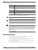
Chapter 1 Introducing the Cisco MXE 3000 Hardware Features Table 1-4 describes the back panel LEDs and their functions. Table 1-4 Back Panel LEDs LED 1 2 NIC/iLO 2 activity NIC/iLO 2 link Color State Description Green On Activity exists. Green Flashing - Off No activity exists. Green On Link exists. - Off No link exists. Location of Ports and Connectors The Cisco MXE 3000 appliance supports two Ethernet connectors on the back of the device.
Chapter 1 Introducing the Cisco MXE 3000 System Board Components and LEDs Figure 1-5 Ethernet Port Connector Link LED (green) 83195 Activity LED (green) 8 1 Serial Port Connector The Cisco MXE 3000 has one serial port connector (shown in Figure 1-6). Use the serial port connector to connect a serial device.
Chapter 1 Introducing the Cisco MXE 3000 System Board Components and LEDs System Board Components Figure 1-7 shows the layout of the system board components.
Chapter 1 Introducing the Cisco MXE 3000 System Board Components and LEDs 17 System maintenance switch 36 Reserved 18 Fan 4 connector 37 Dedicated iLO2 optional module connector 19 System battery — — * The serve supports one optical drive that can be connected to either SATA connector 5 or SATA connector 6. ** x8 PCI Express cards are supported, but will run at x1 speeds. System Board LEDs Figure 1-8 shows the system board LEDs.
Chapter 1 Introducing the Cisco MXE 3000 System Board Components and LEDs Table 1-5 System Board LEDs (continued) LED 5 6 7 8 9 10 11 12 Fan 3 failure PCI fan failure Overtemperature DIMM 4 failure DIMM 3 failure DIMM 2 failure DIMM 1 failure Reserved Color State Description Amber On Fan 3 has failed or is missing. - Off Normal. Amber On PCI fan has failed or is missing. - Off Normal. Amber On System has reached a cautionary or critical temperature level. - Off Normal.
Chapter 1 Introducing the Cisco MXE 3000 System Board Components and LEDs System Board Fans Figure 1-9 shows the location of the system board fans that provide ventilation for the chassis.
CH A P T E R 2 Preparing to Install the Cisco MXE 3000 This chapter contains important safety information that you should know before working with the Cisco MXE 3000. Use the guidelines in this chapter to ensure your own personal safety and to help protect your appliance from potential damage.
Chapter 2 Preparing to Install the Cisco MXE 3000 Safety Guidelines Warning To reduce the risk of electric shock or damage to the equipment: - Do not disable the power cord grounding plug. The grounding plug is an important safety feature. - Plug the power cord into a grounded (earthed) electrical outlet that is easily accessible at all times. - Unplug the power cord from the power supply to disconnect power to the equipment.
Chapter 2 Preparing to Install the Cisco MXE 3000 Safety Guidelines – The product has been exposed to water. – The product has been dropped or damaged. – The product does not operate correctly when you follow the operating instructions. • Keep your system components away from radiators and heat sources. Also, do not block cooling vents. • Do not spill food or liquids on your system components, and never operate the product in a wet environment.
Chapter 2 Preparing to Install the Cisco MXE 3000 Environmental Requirements Working Inside the Cisco MXE 3000 with the Power On The Cisco MXE 3000 is designed to operate safely with the cover removed for short periods (less than 30 minutes). You might need to remove the cover while the power is on, for example, to observe the diagnostic LEDs when troubleshooting. When you work inside an appliance that is powered on, follow these guidelines: • Avoid loose-fitting clothing on your forearms.
Chapter 2 Preparing to Install the Cisco MXE 3000 Power Requirements Power Requirements Installation of this equipment must comply with local and regional electrical regulations governing the installation of information technology equipment by licensed electricians. This equipment is designed to operate in installations covered by NFPA 70, 1999 Edition (National Electric Code) and NFPA-75, 1992 (code for Protection of Electronic Computer/Data Processing Equipment).
Chapter 2 Preparing to Install the Cisco MXE 3000 Grounding Requirements Hardware Installation Guide for Cisco Media Experience Engine 3000 2-6 OL-17000-01
CH A P T E R 3 Installing the Cisco MXE 3000 This chapter describes how to install a Cisco MXE 3000 in an equipment rack.
Chapter 3 Installing the Cisco MXE 3000 Rack-Mounting Parts, Tools, and Considerations Rack-Mounting Parts, Tools, and Considerations A rack mounting hardware kit is included in your shipping container. To mount the Cisco MXE 3000 in the rack, you need a T-10/T-15 Torx screwdriver. Warning To prevent bodily injury when mounting or servicing this unit in a rack, you must take special precautions to ensure that the system remains stable.
Chapter 3 Installing the Cisco MXE 3000 Rack Mounting and Cabling the Cisco MXE 3000 Observe the following additional requirements to ensure adequate airflow and to prevent damage to the equipment: • Front and rear doors—If the 42U rack includes closing front and rear doors, you must allow 5,350 sq cm (830 sq in) of holes evenly distributed from top to bottom to permit adequate airflow (equivalent to the required 64 percent open area for ventilation).
Chapter 3 Installing the Cisco MXE 3000 Checking the LEDs Hardware Installation Guide for Cisco Media Experience Engine 3000 3-4 OL-17000-01
CH A P T E R 4 Installing Hardware Options for the Cisco MXE 3000 This chapter provides basic instructions for installing hardware options in your Cisco MXE 3000. Note These instructions are intended for technicians who are experienced with setting up Cisco MXE 3000 hardware.
Chapter 4 Installing Hardware Options for the Cisco MXE 3000 Removing a Hard Drive Blank Removing a Hard Drive Blank Caution To prevent improper cooling and thermal damage, do not operate the server unless all bays are populated with either a component or a blank. Remove the component, as shown in Figure 4-1.
CH A P T E R 5 Troubleshooting the Cisco MXE 3000 This chapter provides basic troubleshooting information to help you identify some common problems that might occur with your Cisco MXE 3000.
Chapter 5 Troubleshooting the Cisco MXE 3000 Identifying System Problems Identifying System Problems To identify system problems, follow these steps: Step 1 Check the power LED. Step 2 Power down the device and all external devices. Step 3 Check all cables and power cords. (See the “Checking Connections and Switches” section on page 5-2.) Step 4 Set all display controls on the terminal or display device to the middle position. Step 5 Power up all external devices. Step 6 Power up the device.
Chapter 5 Troubleshooting the Cisco MXE 3000 Power-On Self Test (POST) Step 5 Reconnect the system to the electrical outlet or power strip. Make sure that all connections fit tightly together. Step 6 Power up the system. Is the problem resolved? Yes. The connections were loose. You have fixed the problem. No. Call your customer service representative. (See the “Obtaining Documentation and Submitting a Service Request” section on page x.
Chapter 5 Troubleshooting the Cisco MXE 3000 Power-On Self Test (POST) POST Error Codes The error messages and codes in this section include all messages generated by the Cisco MXE 3000 appliance. Some messages are informational only and do not indicate any error. A server generates only the codes that are applicable to its configuration and options.
Chapter 5 Troubleshooting the Cisco MXE 3000 Power-On Self Test (POST) Fan Solution Not Fully Redundant Possible Cause: The minimum number of required fans is installed, but some redundant fans are missing or failed. Action: Install fans or replace failed fans to complete redundancy. Fan Solution Not Sufficient Possible Cause: The minimum number of required fans is missing or failed. Action: Install fans or replace any failed fans.
Chapter 5 Troubleshooting the Cisco MXE 3000 Power-On Self Test (POST) High Temperature Condition detected by Processor X Possible Cause: Ambient temperature exceeds recommended levels, fan solution is insufficient, or fans have failed. Action: Adjust the ambient temperature, install fans, or replace the failed fans. Illegal Opcode - System Halted Possible Cause: The server has entered the Illegal Operator Handler because of an unexpected event.
Chapter 5 Troubleshooting the Cisco MXE 3000 Power-On Self Test (POST) Network Server Mode Active and No Keyboard Attached Possible Cause: A keyboard is not connected. An error has not occurred, but a message is displayed to indicate the keyboard status. Action: No action is required. NMI - Button Pressed! Possible Cause: The NMI button was pressed, initiating a memory dump for crash dump analysis. Action: Reboot the server. NMI - Undetermined Source Possible Cause: An NMI event has occurred.
Chapter 5 Troubleshooting the Cisco MXE 3000 Power-On Self Test (POST) PCI Bus Parity Error, PCI Slot x Possible Cause: A PCI device has generated a parity error on the PCI bus. Action: For plug-in PCI cards, remove the card. For embedded PCI devices, run Insight Diagnostics and replace any failed components as indicated. Power Fault Detected in Hot-Plug PCI Slot x Possible Cause: PCI-X Hot Plug expansion slot was not powered up properly. Action: Reboot the server. Processor X Unsupported Wattage.
Chapter 5 Troubleshooting the Cisco MXE 3000 Power-On Self Test (POST) Action: Populate the DIMM socket. This system only supports 667 MHz Front Side Bus Speed Processors. One or more 800 MHz Front Side Bus Speed Processors have been initialized at 667 MHz. System Halted! Possible cause: One or more 800-MHz front side bus speed processors have been initialized at 667-MHz. Action: Correct the processor configuration. Unsupported DIMM(s) found in system.
Chapter 5 Troubleshooting the Cisco MXE 3000 Power-On Self Test (POST) Action: Step 1 Power down the server, and then reconnect the keyboard. Step 2 Be sure no keys are depressed or stuck. Step 3 If the failure reoccurs, replace the keyboard. 301-Keyboard Error or Test Fixture Installed Possible Cause: Keyboard failure occurred. Action: Step 1 Power down the server, and then reconnect the keyboard. Step 2 Be sure no keys are depressed or stuck.
Chapter 5 Troubleshooting the Cisco MXE 3000 NMI Functionality NMI Functionality An NMI crash dump enables administrators to create crash dump files when a system is hung and not responding to traditional debug mechanisms. Crash dump log analysis is an essential part of diagnosing reliability problems, such as hangs in operating systems, device drivers, and applications. Many crashes freeze a system, and the only available action for administrators is to cycle the system power.
Chapter 5 Troubleshooting the Cisco MXE 3000 Troubleshooting Undetermined Problems Table 5-1 System LED and Internal LED Color Combinations and Statuses System LED and Color Internal Health LED Color DIMM failure, slot X (amber) Red — Amber Status • DIMM in slot X has failed. • DIMM in slot X is an unsupported type, and no valid memory exists in another bank. • DIMM in slot X has reached single-bit correctable error threshold. • DIMM in slot X is in a pre-failure condition.
Chapter 5 Troubleshooting the Cisco MXE 3000 General Problem-Solving Tips • Modem, printer, mouse, or non-Cisco devices • Each adapter • Disk drives • Memory modules (minimum requirement = 4 GB; two banks of 2 GB DIMMs) Note Step 4 Any component that is internal to the device, with the exception of customer-replaceable adapters, must be serviced by trained and qualified personnel. Contact your customer service representative. Power up the device.
Chapter 5 Troubleshooting the Cisco MXE 3000 General Problem-Solving Tips • Improperly seated or faulty power supply • Loose or faulty power cord • Power source problem • Power on circuit problem • Improperly seated component or interlock problem • Faulty internal component See the “Checking Connections and Switches” section on page 5-2. POST Problems Symptoms: • Note • Server does not complete POST The server has completed POST when the system attempts to access the boot device.
Chapter 5 Troubleshooting the Cisco MXE 3000 Collecting Information for Technical Support Collecting Information for Technical Support Because of the variety of hardware and software combinations that can be encountered, use the following information to assist you in identifying the problems. Have this information available when requesting technical assistance. For information about submitting a service request, see the “Obtaining Documentation and Submitting a Service Request” section on page x.
Chapter 5 Troubleshooting the Cisco MXE 3000 Collecting Information for Technical Support Hardware Installation Guide for Cisco Media Experience Engine 3000 5-16 OL-17000-01
A P P E N D I X A Cisco MXE 3000 Hardware Specifications This appendix provides hardware specifications for the Cisco MXE 3000 appliance. It contains the following sections: • Environmental Specifications, page A-1 • Server Specifications, page A-2 Environmental Specifications Table A-1 provides the environmental specifications for the Cisco MXE 3000 appliance.
Appendix A Cisco MXE 3000 Hardware Specifications Server Specifications Table A-1 Environmental Specifications Operating 457 m/min (1,500 ft/min) Non-operating 457 m/min (1,500 ft/min) 1. All temperature ratings shown are for sea level. An altitude derating of 1°C per 300 m (1.8°F per 1,000 ft) to 3048 m (10,000 ft) is applicable. No direct sunlight allowed. 2. The type and number of options installed can limit the upper limit. 3.
Appendix A Cisco MXE 3000 Hardware Specifications Server Specifications 1. The limits apply when operated in an ambient environment temperature of +23.0°C ± 2° (+73.4°F ± 2°). 2. Average A-Weighted sound power levels (LWAd) and average bystander position A-Weighted sound pressure levels (LpAm) in a 23°C ambient environment, measured in accordance with ISO 7779 (ECMA 74) and declared in accordance with ISO 9296 (ECMA 109). Acoustic noise levels are maximum measurements with four fans installed.
Appendix A Cisco MXE 3000 Hardware Specifications Server Specifications Hardware Installation Guide for Cisco Media Experience Engine 3000 A-4 OL-17000-01
A P P E N D I X B Maintaining the Cisco MXE 3000 Proper use of preventive maintenance procedures can keep the Cisco MXE 3000 in good operating condition and minimize the need for costly, time-consuming service procedures. This chapter contains maintenance procedures that you should perform regularly.
Appendix B Maintaining the Cisco MXE 3000 Maintaining Your Site Environment Temperature Temperature extremes can cause a variety of problems, including premature aging and failure of chips or mechanical failure of devices. Extreme temperature fluctuations can cause chips to become loose in their sockets and can cause expansion and contraction of disk drive platters, resulting in read or write data errors.
Appendix B Maintaining the Cisco MXE 3000 Maintaining Your Site Environment Dust and Particles A clean operating environment can greatly reduce the negative effects of dust and other particles, which act as insulators and interfere with the operation of a system’s mechanical components. In addition to regular cleaning, you should follow these guidelines to deter contamination of the system equipment: • Do not permit smoking anywhere near the system. • Do not permit food or drink near the system.
Appendix B Maintaining the Cisco MXE 3000 Maintaining Your Site Environment RFI is defined as any EMI with a frequency above 10 kilohertz (kHz). This type of interference can travel from the system to other devices through the power cable and power source or through the air like transmitted radio waves. The Federal Communications Commission (FCC) publishes specific regulations to limit the amount of EMI and RFI emitted by computing equipment. Each system meets these FCC regulations.
Appendix B Maintaining the Cisco MXE 3000 Using Power Protection Devices – Copier machines – Air conditioners – Vacuum cleaners – Space heaters – Power tools – Teletype machines – Adding machines – Laser printers – Facsimile machines – Any other motorized equipment Besides these appliances, the greatest threats to a system’s supply of power are surges or blackouts caused by electrical storms.
Appendix B Maintaining the Cisco MXE 3000 Using Power Protection Devices Uninterruptible Power Supplies Uninterruptible power supply (UPS) systems offer the most complete protection against variations in power because they use battery power to keep the system running when AC power is lost.
INDEX environment A maintaining altitude B-1 ESD guidelines B-2 preventing damage 2-4, B-3 Ethernet port connector pinouts C connections power F 3-3 troubleshooting 5-2 flowcharts connectors and ports locations 1-6 5-13, 5-14 front panel 1-5 figure 1-2 corrosion preventing damage B-3 H cover removing 4-1 hardware troubleshooting 5-1 humidity D maintenance guidelines B-2 DC power installation precautions diagnosing problems 2-3 I 5-13 dust I/O connectors preventing dam
Index troubleshooting 5-11 LEDs, troubleshooting R 5-13 radio frequency interference Light Path Diagnostics using See RFI 5-11 RFI line conditioners using preventing effects of B-5 M S magnetism safety preventing effects of maintenance B-3 general precautions B-4 warnings B-1 to B-5 2-2 2-1 serial port MXE installing connector pinout 3-3 description 1-6 1-6 server fault indications flowchart P 5-14 shock preventing damage ports Ethernet serial B-4 site environment 1-5
Index trouble indicators 5-11 undetermined problems troubleshooting sequence 5-12 5-13 U undetermined problems troubleshooting 5-12 uninterruptible power supplies using B-6 V vibration preventing damage B-4 W warnings installation 2-1 working inside MXE with power on 2-4 Hardware Installation Guide for Cisco Media Experience Engine 3000 OL-17000-01 IN-3
Index Hardware Installation Guide for Cisco Media Experience Engine 3000 IN-4 OL-17000-01