Cisco MWR 1900 Mobile Wireless Edge Router Hardware Installation Guide Corporate Headquarters Cisco Systems, Inc. 170 West Tasman Drive San Jose, CA 95134-1706 USA http://www.cisco.
THE SPECIFICATIONS AND INFORMATION REGARDING THE PRODUCTS IN THIS MANUAL ARE SUBJECT TO CHANGE WITHOUT NOTICE. ALL STATEMENTS, INFORMATION, AND RECOMMENDATIONS IN THIS MANUAL ARE BELIEVED TO BE ACCURATE BUT ARE PRESENTED WITHOUT WARRANTY OF ANY KIND, EXPRESS OR IMPLIED. USERS MUST TAKE FULL RESPONSIBILITY FOR THEIR APPLICATION OF ANY PRODUCTS.
C O N T E N T S About This Guide Objectives Audience v v v Organization v Conventions vi Obtaining Documentation World Wide Web viii viii Ordering Documentation ix Documentation Feedback ix Obtaining Technical Assistance Cisco.
Contents Console and Auxiliary Port Considerations Console Port Connections 2-6 Auxiliary Port Connections CHAPTER Installing the Router 3 2-6 2-6 3-1 Rack Mounting the Chassis 3-1 Attaching the Brackets 3-2 Installing the Router in the Rack 3-2 Installing a T1/E1 Multiflex VWIC 3-2 Connecting the Console Terminal and Modem Identifying a Rollover Cable Console Port 3-2 3-3 3-3 Auxiliary Port 3-4 Connecting the Network Cables 3-4 Connecting the FE Interface Cables 3-4 Connecting t
About This Guide This preface discusses the objectives, audience, organization, and conventions of this hardware installation guide. Objectives This guide explains how to install, maintain, and troubleshoot your router hardware. Although this guide provides minimum software configuration information, it is not comprehensive. For detailed software configuration information, see the Cisco IOS configuration guide and command reference publications. (See “Obtaining Documentation” for more information.
About This Guide Conventions Chapter Title Description Chapter 3 Installing the Router Includes router installation information, and shows how to connect to the router console, auxiliary, and network ports. Appendix A Troubleshooting Describes how to isolate problems, read LEDs, interpret error and status messages, recover an enable password, and recover software images.
About This Guide Conventions Safety warnings appear throughout this publication in procedures that, if performed incorrectly, may harm you. A warning symbol precedes each warning statement. Warning This warning symbol means danger. You are in a situation that could cause bodily injury. Before you work on any equipment, be aware of the hazards involved with electrical circuitry and be familiar with standard practices for preventing accidents.
About This Guide Obtaining Documentation Advarsel Dette varselsymbolet betyr fare. Du befinner deg i en situasjon som kan føre til personskade. Før du utfører arbeid på utstyr, må du vare oppmerksom på de faremomentene som elektriske kretser innebærer, samt gjøre deg kjent med vanlig praksis når det gjelder å unngå ulykker.
About This Guide Obtaining Technical Assistance Ordering Documentation Cisco documentation is available in the following ways: • Registered Cisco Direct Customers can order Cisco Product documentation from the Networking Products MarketPlace: http://www.cisco.com/cgi-bin/order/order_root.pl • Registered Cisco.com users can order the Documentation CD-ROM through the online Subscription Store: http://www.cisco.com/go/subscription • Nonregistered Cisco.
About This Guide Obtaining Technical Assistance Customers and partners can self-register on Cisco.com to obtain additional personalized information and services. Registered users can order products, check on the status of an order, access technical support, and view benefits specific to their relationships with Cisco. To access Cisco.com, go to the following website: http://www.cisco.
C H A P T E R 1 Overview of the Cisco MWR 1900 Router The MWR 1900 Mobile Wireless Edge Router is a networking platform optimized for use in mobile wireless networks.
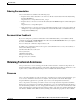
Chapter 1 Overview of the Cisco MWR 1900 Router Hardware Features Figure 1-1 MWR 1900 in an IP-RAN Solution Active 100BaseT T1/E1 backhaul link to IP RAN aggregation node Standby MWR 1900 IP BTS router pair 65827 pBTS In the IP-RAN solution, the BTS site consists of a pair of MWR 1900 routers. The pair of MWR 1900 routers provides for an active and standby router for redundancy. A failure of the active MWR 1900 router causes the standby router to take over as the active router for the BTS site.
Chapter 1 Overview of the Cisco MWR 1900 Router Hardware Features Figure 1-2 Front Panel of the Cisco MWR 1900 Router VWIC LEDs: Alarm (A) Loopback (A) Carrier detect (G) Fast ethernet LEDs: Activity (G) Speed (G) VWIC Link (G) position 2 SEE MAN UAL BEFO RE INST ALLATION VWIC LEDs: Alarm (A) Loopback (A) Carrier detect (G) VWIC position 0 2 ports DSU 56K SEE MAN UAL BEFO RE INST ALLATION Figure 1-3 2 FE ports Compact flash slot E AUXILIA RY Air vent (both sides) Console port VWIC position
Chapter 1 Overview of the Cisco MWR 1900 Router Fast Ethernet Interfaces • Redundancy support via a two T1/E1 WIC capable of port switching ON/OFF via relays • Console RS-232 port • Auxiliary Serial Port with hardware flow control • Extended operational temperature range from -10ºC to + 55ºC with over-temperature sensor • Front (connector side) to rear airflow using four 40mm, 10 CFM exhaust fans • Custom +27V DC input power • Three green chassis LEDs for Power (PS is operational), System Re
Chapter 1 Overview of the Cisco MWR 1900 Router Compact Flash Compact Flash One external Compact Flash (CF) device is used on the MWR 1900 router. The CF memory size can vary with a minimum size of 32Mbyte and a maximum size of 128Mbytes. This device is configured in memory mapped mode (PCMCIA) to allow for hot insertion. This device is required for the MWR 1900 router to function because the IOS image and troubleshooting logs reside on this device.
Chapter 1 Overview of the Cisco MWR 1900 Router Environmental Monitoring Temperature Sensor Environmental Monitoring Temperature Sensor The MWR 1900 router has a temperature sensor to detect over-temperature conditions inside the chassis. The over-temperature detection trips at 75°C +/- 5%. This condition is reported to the processor as an interrupt and software then takes action on this interrupt to generate the appropriate alarming.
C H A P T E R 2 Preparing to Install the Router This chapter describes site requirements and equipment needed to install your Cisco MWR 1900 router.
Chapter 2 Preparing to Install the Router Safety Recommendations Safety with Electricity Warning Before performing any of the following procedures, ensure that power is removed from the DC circuit. To ensure that all power is OFF, locate the circuit breaker on the panel board that services the DC circuit, switch the circuit breaker to the OFF position, and tape the switch handle of the circuit breaker in the OFF position. Warning This unit is intended for installation in restricted access areas.
Chapter 2 Preparing to Install the Router General Site Requirements – If possible, send another person to get medical aid. Otherwise, determine the condition of the victim and then call for help. – Determine if the person needs rescue breathing or external cardiac compressions; then take appropriate action. General Site Requirements You can mount the Cisco MWR 1900 router in a 19-inch rack (with a 17.5- or 17.75-inch opening).
Chapter 2 Preparing to Install the Router Inspecting the Router • #6, ring-style ground lug. • 18-AWG copper wire for the power cord. • Wire-stripping tool(s) for stripping both 6- and 18-gauge wires. Inspecting the Router Do not unpack the router until you are ready to install it. If the final installation site will not be ready for some time, keep the chassis in its shipping container to prevent accidental damage. When you are ready to install the router, proceed with unpacking it.
Chapter 2 Preparing to Install the Router Installation Checklist Installation Checklist The sample Installation Checklist lists items and procedures for installing a new router. Make a copy of this checklist and mark the entries when completed. Include a copy of the checklist for each router in your Site Log (described in the next section, “Console and Auxiliary Port Considerations”).
Chapter 2 Preparing to Install the Router Console and Auxiliary Port Considerations Console and Auxiliary Port Considerations The router includes an asynchronous serial console port and an auxiliary port. The console and auxiliary ports provide access to the router either locally using a console terminal, or remotely using a modem connected to the auxiliary port.
C H A P T E R 3 Installing the Router This chapter describes how to install your Cisco MWR 1900 router and connect it to networks and external devices.
Chapter 3 Installing the Router Connecting the Console Terminal and Modem Attaching the Brackets Attach the mounting brackets to the chassis as shown, using the screws provided in the bracket kit. Attach the second bracket to the opposite side of the chassis. Use a number 2 Phillips screwdriver to install the bracket screws. Four screws are required on each side. Figure 3-1 shows how the bracket is attached.
Chapter 3 Installing the Router Connecting the Console Terminal and Modem These ports provide administrative access to your router either locally (with a console terminal) or remotely (with a modem). Identifying a Rollover Cable Use a rollover cable to connect to the asynchronous serial console and auxiliary ports. You can identify a rollover cable by comparing the two modular ends of the cable.
Chapter 3 Installing the Router Connecting the Network Cables Note Because hardware flow control is not possible on the console port, Cisco does not recommend that modems be connected to the console port. Modems should always be connected to the auxiliary port. Auxiliary Port Take the following steps to connect a modem to the auxiliary port on the router: Step 1 Connect a modem to the auxiliary port using an RJ-45 rollover cable with an RJ-45-to-DB-25 adapter. The provided adapter is labeled MODEM.
Chapter 3 Installing the Router Connecting the Network Cables RJ-45 Port and Plug H2936 Figure 3-3 87654321 RJ-45 connector Table 3-1 lists the pinouts and signals for the RJ-45 port. Table 3-1 RJ-45 Pinout Pin Description 1 Receive Data + (RxD+) 2 RxD- 3 Transmit Data + (TxD+) 6 TxD- Connecting the VWIC Interface Cables How you connect the ports of the T1/E1 Multiflex VWIC depends on whether you are using the MWR 1900 router in a redundant or a non-redundant configuration.
Chapter 3 Installing the Router Connecting the Network Cables Note If you choose to use the T1/E1 Multiflex VWIC in a non-redundant configuration, you must close the relays on the card using the standalone subcommand. For more information, see the “Cisco MWR 1900 Software Configuration Guide.” Step 1 Confirm that the router is turned off. Step 2 Connect one end of the cable to the T1 or E1 port on the card. Step 3 Connect the other end to the BTS patch or demarcation panel at your site.
Chapter 3 Installing the Router Connecting the MWR 1900 Router to a DC-Input Power Supply This section describes the specifications of the Y-cable. • T1/E1 Multiflex VWIC Y-cables should be made with 4 twisted-pair, shielded, 28-gauge cables. • The cable length of each stub (from the RJ-48C connector to the junction point) should not exceed 3 inches (76 mm). • The cable length from junction point to the patch panel is determined by the customer.
Chapter 3 Installing the Router Connecting the MWR 1900 Router to a DC-Input Power Supply • 18-AWG copper wire for the power cord. • Wire-stripping tool(s) for stripping both 6- and 18-gauge wires. Grounding the Router Follow these steps to ground the router to earth ground. Make sure to follow any grounding requirements at your site. Warning This equipment is intended to be grounded. Ensure that the host is connected to earth ground during normal use.
Chapter 3 Installing the Router Connecting the MWR 1900 Router to a DC-Input Power Supply Step 6 Use the screw to attach the ground lug and wire assembly to the rear panel of the switch. Step 7 Using a ratcheting torque screwdriver, torque the ground-lug screw to 15 1bf-in (or 240 ounce-force inches [240 ozf-in]). Wiring the DC-Input Power Source Warning Note This product relies on the building’s installation or power supply for short circuit (overcurrent) protection.
Chapter 3 Installing the Router Replacing or Upgrading the CF Warning After wiring the DC power supply, remove the tape from the circuit breaker switch handle and reinstate power by moving the handle of the circuit breaker to the ON position. Warning Do not touch the power supply when the power cord is connected. For systems with a power switch, line voltages are present within the power supply even when the power switch is off and the power cord is connected.
Chapter 3 Installing the Router Replacing or Upgrading the CF Note Ensure that the IOS image is the first file on the CF. Otherwise, the router will not boot. To avoid naming conflicts, we recommend that you copy the file as mwr1900-i-mz.boot. Step 9 Reboot the system to the ROMMON prompt. Step 10 Boot the customer-ordered IOS image from the new CF. Step 11 Upon successful booting of the image, replace the CF cover. If the boot process is unsuccessful, repeat Step 6 through Step 10.
Chapter 3 Installing the Router Replacing or Upgrading the CF Formatting Procedures for CF Memory Cards For the Cisco MWR 1900 router, Cisco recommends that you format/erase new CF memory cards to initialize them with a Class C Flash file system. This ensures proper formatting and enables the ROM monitor to recognize and boot the Flash.
Chapter 3 Installing the Router Replacing or Upgrading the CF The following example shows output for copying a Cisco IOS file from an external CF memory card to a TFTP server: Router# copy slot0:mwr1900-i-mz.tmp tftp: Destination filename [mwr1900-i-mz.
Chapter 3 Installing the Router Replacing or Upgrading the CF The following example shows output for displaying the geometry and format information of an external CF memory card formatted with a Class C Flash file system: Router# show slot0: ******** ATA Flash Card Geometry/Format Info ******** ATA CARD GEOMETRY Number of Heads: 2 Number of Cylinders 490 Sectors per Cylinder 32 Sector Size 512 Total Sectors 31360 ATA CARD FORMAT Number of FAT Sectors Sectors Per Cluster Number of Clusters Number of Data
Chapter 3 Installing the Router Replacing or Upgrading the CF Display File Content To display the content of a file in a CF memory card, use the more slot0: filename command. The following example shows output from the more command on an external CF card: Router# more slot0:mwr1900-i-mz.
Chapter 3 Installing the Router What to Do After Installing the Hardware Router# cd slot0:/config Router# dir slot0: Directory of slot0:/config/ 1581 drw- 0 Mar 01 1993 23:50:08 test-config 128094208 bytes total (121626624 bytes free) Remove a Directory To remove a directory from CF memory, use the rmdir slot0:/directory-name command. Before you can remove a directory, all files and subdirectories must be removed from the directory.
A P P E N D I X A Troubleshooting Your Cisco MWR 1900 router goes through extensive testing before leaving the factory. If you encounter problems, use the information in this appendix to help isolate problems or to eliminate the router as the source of the problem. This appendix contains the following sections: • Problem Solving, page A-1 • Reading the LEDs, page A-3 If you cannot locate the source of the problem, contact a customer service representative for information on how to proceed.
Appendix A Troubleshooting Problem Solving Troubleshooting the Power and Cooling Systems Both the power LED and the fans can help you troubleshoot a power problem. Check the following items to help isolate the problem: Check the following items to help isolate problems with the power supply installation: • With the MWR 1900 router connected to the power source, is the power LED on the front panel on? – If not, check the DC input, DC source, and the power supply wiring.
Appendix A Troubleshooting Reading the LEDs Troubleshooting Modules, Cables, and Connections Network problems can be caused by a module, cables or cable connections, or external devices such as a modem, transceiver, hub, wall jack, WAN interface, or terminal. Check for the following symptoms to help isolate the problem: • Module is not recognized by the router. – Make sure the module is firmly seated in its slot. – Check the LEDs on the module. Each module has its own set of LEDs.
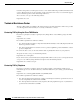
Appendix A Troubleshooting Reading the LEDs Figure A-1 Front Panel of the MWR 1900 VWIC LEDs: Alarm (A) Loopback (A) Carrier detect (G) Fast ethernet LEDs: Activity (G) Speed (G) VWIC Link (G) position 2 SEE MAN UAL BEFO RE INST ALLATION VWIC LEDs: Alarm (A) Loopback (A) Carrier detect (G) VWIC position 0 2 ports DSU 56K SEE MAN UAL BEFO RE INST ALLATION Table A-1 2 FE ports Compact flash slot E AUXILIA RY Air vent (both sides) Console port VWIC position 1 2 ports Auxiliary port Power (G
Appendix A Troubleshooting Reading the LEDs Table A-3 VWIC LEDs LED Color Description Loopback Amber A loopback or line state is detected or is manually set by the user. Off Normal operation. Amber A local or remote alarm state. Off Normal operation. Alarm Carrier Detect Green Off Note A carrier has been detected and the internal DSU/CSU in the WAN interface card is communicating with another DSU/CSU. This LED is on during normal operation. No carrier has been detected.
Appendix A Troubleshooting Reading the LEDs Cisco MWR 1900 Mobile Wireless Edge Router Hardware Installation Guide A-6 78-13982-02
I N D E X network cables Numerics power supply 2-port T1/E1 VWIC connecting 3-5 description 1-4 3-4 3-7 VWIC interface cables 3-5 console port connections pinout specifications 3-6 2-6, 3-2, 3-3 considerations 2-6 conventions, documentation vi A audience D v auxiliary port connecting dimensions, chassis 3-4 connections documentation 2-6, 3-4 considerations 1-6 conventions 2-6 obtaining vi viii organization v B back panel E 1-3 equipment for installation C racks chass
Index G P general site requirements packing list 2-3 2-4 pinout specifications fast ethernet H VWIC 3-6 powering on hardware features 3-9 power supply 1-2 installing 3-5 3-1 troubleshooting procedures A-1 connecting 3-7 description 1-5 warnings 3-9 problem solving I See troubleshooting installation checklist 2-5 compact flash hardware R 3-11 rack-mounting 3-1 rack-mounting tools required brackets 3-1 equipment 2-3 fast ethernet, description VWIC, description regulat
Index system installation procedures system specifications 3-4 1-6 T tools required for installation 2-3 troubleshooting cables A-3 connections A-3 cooling system A-2 front panel LEDs modules A-3 A-3 power system A-2 U upgrading compact flash 3-10 V ventilation 2-3 VWIC See 2-port T1/E1 VWIC W warning access to plug-socket 3-9 DC power connection 3-10 exposed wires grounding 3-9 3-10 power supply 3-10 restricted access 3-7 restricted area 3-7 secure cabling 3-9 short cir
Index Cisco MWR 1900 Mobile Wireless Edge Router Hardware Installation Guide IN-4 78-13982-02