
Network Router User Manual


4-24
Cisco ONS 15454 SDH Procedure Guide, R4.6
January 2004
Chapter 4 Turn Up Node
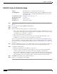
DLP-D69 Set Up External or Line Timing
• E1, 2.048 MHz, 64 KHz—Choose E1, 2.048 MHz, or 64 KHz depending on the signal supported
in your market. For example, 64 KHz is used in Japan. E1, 2.048 MHz, and 64 KHz are physical
signal modes used to transmit the external clock (from a global positioning satellite [GPS], for
example) to BITS.
• BITS In State—If Timing Mode is set to External or Mixed, set the BITS In State for BITS-1 and/or
BITS-2 to IS (in service) depending whether one or both BITS input pin pairs on the backplane are
connected to the external timing source. If Timing Mode is set to Line, set the BITS In State to OOS
(out of service).
• BITS Out State—If equipment is connected to the node’s BITS output pins on the backplane and
you want to time the equipment from a node reference, set the BITS Out State for BITS-1 and/or
BITS-2 to IS, depending on which BITS Out pins are used for the external equipment. If equipment
is not attached to the BITS output pins, set the BITS Out State to OOS.
Step 4 If the BITS In State for BITS-1 and BITS-2 is set to OOS, continue with Step 5. If the BITS In State is
set to IS for either BITS-1 or BITS-2, complete the following information:
• Coding—Choose the coding used by your BITS reference, either HDB3 or AMI (alternate mark
inversion). If you selected 2.048 MHz or 64 KHz, the coding option is disabled.
• Framing—Choose the framing used by your BITS reference, either unframed, FAS, FAS + CAS,
FAS + CRC, or FAS + CAS + CRC. If you selected 2.048 MHz or 64 KHz, the framing option is
disabled.
• Sync Messaging—Select the check box to enable synchronization status messaging (SSM). SSM is
used to deliver clock quality. The SSM supported in SDH is G811, STU, G812T, G812L, SETS,
DUS (ordered from high quality to low quality). If you selected 2.048 MHz or 64 KHz, the SSM
option is disabled.
• AIS Threshold—Sets the quality level at which a node sends an alarm indication signal (AIS) from
the BITS-1 Out and BITS-2 Out FMEC connectors. When a node times at or below the AIS
threshold quality, an AIS is raised. (The AIS threshold is used when SSM is disabled or framing is
set to unframed, FAS, or FAS + CAS.)
• LBO—Choose a BITS cable length. Line build out (LBO) relates to the BITS cable length.
• Sa bit—Choose one of 5 Sa bits (Sa4, Sa5, Sa6, Sa7,orSa8). The Sa bit transmits the SSM message.
If you selected 2.048 MHz or 64 KHz, the Sa bit option is disabled.
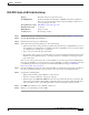
Step 5 In the Reference Lists area, complete the information:
Note Reference lists define up to three timing references for the node and up to six BITS Out
references. BITS Out references define the timing references used by equipment attached to the
node’s MIC-C/T/P FMEC Timing A and Timing B Out connectors. If you attach equipment to
the Timing A Out or Timing B Out connector, you normally attach it to a node with line mode
because equipment near the external timing reference can be directly wired to the reference.
• NE Reference—Allows you to define three timing references (Ref 1, Ref 2, Ref 3). The node uses
Reference 1 unless a failure occurs to that reference, in which case the node uses Reference 2. If
Reference 2 fails the node uses Reference 3, which is typically set to Internal Clock. The internal
clock is the Stratum 3 clock provided on the TCC2. The options displayed depend on the Timing
Mode setting.
–
Timing Mode set to External—Your options are BITS-1, BITS-2, and Internal Clock.