
Network Router User Manual

8
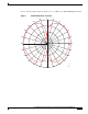
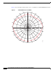
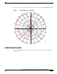
Cisco Multiband Diversity Omnidirectional Ceiling-Mount Antenna (AIR-ANTM4050V-R)
OL-6485-01
Installation Notes
Installation Notes
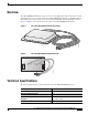
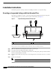
This antenna is designed to be mounted indoors on a suspended ceiling track having either flush or
recessed mounted ceiling tiles.
Because antennas transmit and receive radio signals, they are susceptible to radio frequency (RF)
obstructions and common sources of interference that can reduce throughput and range of the device to
which they are connected. Follow these guidelines to ensure the best possible performance:
• Mount the antenna to use its propagation characteristics. For best results, mount the antenna
horizontally at ceiling level near the center of the coverage area.
Note The antenna must be mounted horizontally in order to maximize its omnidirectional
propagation characteristics. Mounting it vertically may noticeably decrease the antenna
range and overall performance.
• Mount the antenna where the wireless devices would be within sight. Avoid mounting the antenna
next to a column or vertical support that could create a shadow zone and reduce the coverage area.
• Keep the antenna away from metal obstructions such as heating and air-conditioning ducts, large
ceiling trusses, building superstructures, and major power cabling runs. If necessary, use a rigid
conduit to lower the antenna away from these obstructions.
• The density of the materials used in a building’s construction determines the number of walls the
signal must pass through and still maintain adequate coverage. Consider the following before
choosing the location to install your antenna:
–
Paper and vinyl walls have very little effect on signal penetration.
–
Solid and precast concrete walls limit signal penetration to one or two walls without degrading
coverage.
–
Concrete and wood block walls limit signal penetration to three or four walls.
–
A signal can penetrate five or six walls constructed of drywall or wood.
–
A thick metal wall causes signals to reflect off, causing poor penetration.
• Install the antenna away from microwave ovens and 2-GHz cordless phones. These products can
cause signal interference because they operate in the same frequency range as the device to which
your antenna is connected.
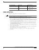
• To extend the coaxial cable included with your antenna, we recomend a low-loss or ultra-low-loss
coaxial cable for installation flexibility without a significant loss in range. The following table lists
transmission loss information about low-loss and ultra-low-loss extension coaxial cables available
from Cisco.
Cisco Product Number Cable Length Transmission Loss
AIR-CAB020LL-R 20 ft (6 m) • 2.4-GHz: 1.3 dBi
• 5-GHz: 2.5 dBi
AIR-CAB050LL-R 50 ft (15 m) • 2.4-GHz: 3.3 dBi
• 5-GHz: 5.75 dBi