
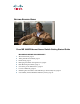
Ethernet Access Switch Getting Started Guide


6
Step 1
Obtain this information from your network
administrator before you start the setup program.
• Switch IP address
• Subnet mask (IP netmask)
• Default gateway (router)
• Enable secret password
• Enable password
• Telnet password
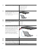
Step 2
Connect the adapter cable to the console
connector on the switch front panel. Connect the
other end of the cable to the Ethernet port on
your DHCP-enabled PC.
You must supply the console cable if you did not
order one with your switch.
Step 3
Start a terminal-emulation application such as Hyperterminal or ProcommPlus.
Step 4
Configure the baud rate and character format of
the PC or terminal to match these console port
default characteristics.
• 9600 baud
• 8 data bits
• 1 stop bit
• No parity
• None (flow control)
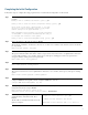
Step 5
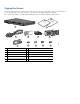
Connect the switch to a power source. For
information on power usage, see the technical
specifications in the hardware installation guide.
This illustration shows a DC-powered switch.
Connect one DC terminal block to the power
connector on the switch front panel. Connect the
other end of the cable to a DC outlet.
For detailed instructions about connecting to an
AC or DC power source, see “Chapter 3,
Installing and Removing the Power-Supply
Modules,” in the hardware installation guide.
Step 6
Power on the switch.
Step 7
Wait for the switch to complete POST. It might take several minutes for the switch to complete POST.
Step 8
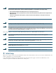
Verify that POST has completed. The System
(SYST) LED blinks green while the switch starts
up. It turns solid green after POST succeeds. If the
switch fails POST, the System LED turns amber.
Contact Cisco Systems immediately if your switch fails POST.
Step 9
When you see the prompt, press Return or Enter.
Press RETURN to get started!
281100
281101