
Network Device Installation Guide

Send documentation comments to mdsfeedback-doc@cisco.com.
1-8
Cisco MDS 9500 Series Hardware Installation Guide
OL-17467-02
Chapter 1 Product Overview
Backplane and Clock Modules
Backplane and Clock Modules
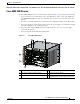
The Cisco MDS 9500 Series includes one or more clock modules that are accessible from the back of
the chassis. The Cisco MDS 9513 and 9509 Directors have two field-replaceable clock modules for
redundancy and failover. The Cisco MDS 9506 Director has one field-replaceable clock module. In the
unlikely event of a clock module failure, the Cisco MDS 9500 Series generates an error message and a
switchover from one clock module to the other, causing the system to reset automatically. Cisco
recommends that the failed clock module be replaced during a maintenance window. See the
“Removing
and Installing Clock Modules” section on page 2-76 for information on replacing clock modules.
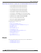
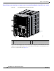
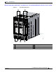
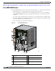
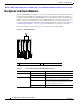
There are two LEDs per clock module. Figure 1-5 shows the upper and lower LEDs.
Figure 1-5 Clock Module LEDs
1 Lower LEDs 2 Upper LEDs
Ta b l e 1-1 Clock LEDs for the Cisco MDS 9500 Series Directors
LED Status Description
Upper LED Green Clock module is active and in use.
Off Clock module is in standby mode.
Lower LED Green Power supply is on and working properly.
Red Power supply is not in a stable state. If this
indication continues after initial power on, check
that all connections are secure.
Off Normal operation or power supply is turned off.
181336
1
2
CLOCK A CLOCK B