
Network Device Installation Guide

Send documentation comments to mdsfeedback-doc@cisco.com.
1-7
Cisco MDS 9500 Series Hardware Installation Guide
OL-17467-02
Chapter 1 Product Overview
Chassis
Cisco MDS 9506 Director
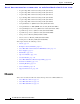
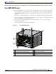
The Cisco MDS 9506 Director has a 6-slot chassis as shown in Figure 1-4, and it supports the following:
• Up to two Supervisor-1 modules that provide a switching fabric, with a console port, COM1 port,
and a MGMT 10/100 Ethernet port on each module. Slots 5 and 6 are reserved for the supervisor
modules.
• Four slots for optional modules that can include up to four switching modules or three IPS modules.
• Two power supplies located in the back of the chassis. The power supplies are redundant by default
and can be configured to be combined if desired.
• Two power entry modules (PEMs) in the front of the chassis for easy access to power supply
connectors and switches.
• One hot-swappable fan module with redundant fans.
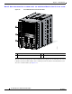
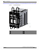
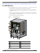
Figure 1-4 Cisco MDS 9506 Chassis
1 Switching or services modules in slots 1–4 4 ESD Socket
2 Supervisor modules in slots 5 and 6 5 Power supplies (in back)
3 Fan module 6 Location of power entry modules (PEMs) --
one PEM shown and one filler panel shown.
91580
1
2
3
4
6
5