
Network Device Installation Guide

Send documentation comments to mdsfeedback-doc@cisco.com.
D-4
Cisco MDS 9500 Series Hardware Installation Guide
OL-17467-02
Appendix D Technical Specifications
Module Specifications
Module Specifications
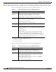
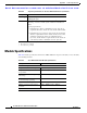
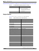
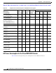
Table D-5 lists the specifications for the Cisco MDS 9500 Series supervisor modules, services modules,
and switching modules.
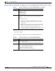
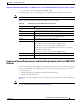
Power supply 1900-W, AC input
1900-W, DC input
Airflow 300 lfm
2
through system fan module, or 80 cfm
3
per supervisor,
switching, or services module (total of 480 cfm if all slots are
filled).
Spacing requirements:
• If installed in a cabinet, a minimum of 2.5 in. (6.4 cm) is
required between the chassis air vents and the cabinet walls.
• If installed in an open rack (no side panels), the horizontal
distance required between the chassis and any devices that
exhaust air towards the chassis is a minimum of 6 in.
(15.2
cm), and the distance required between the chassis air
vents and any walls is a minimum of 2.5 in. (6.4
cm).
1. RU = rack unit; 1 RU = 1.75 in. (4.45 cm)
2. lfm = linear feet per minute
3. cfm = cubic feet per minute
Table D-4 Physical Specifications for the Cisco MDS 9506 Director (continued)
Description Specification
Ta b l e D-5 Cisco MDS 9500 Series Module Specifications
Description Specification
Environmental Requirements
Temperature, certified for operation 32 to 104°F (0 to 40°C)
Temperature, designed and tested
for operation
32 to 130°F (0 to 55°C)
Temperature, ambient nonoperating
and storage
-40 to 167°F (-40 to 75°C)
Humidity (RH), ambient
(noncondensing) operating
10 to 90%
Altitude, certified for operation 0 to 6500 ft (0 to 2000 m)
Altitude, designed and tested for
operation
-200 to 10000 ft (-60 to 3000 m)
Physical Characteristics