
Network Device Installation Guide

Send documentation comments to mdsfeedback-doc@cisco.com.
2-80
Cisco MDS 9500 Series Hardware Installation Guide
OL-17467-02
Chapter 2 Installing the Cisco MDS 9500 Series
Removing and Installing Clock Modules
• OUTPUT FAIL LED is off.
Removing a Clock Module from the Cisco MDS 9509 Director
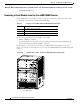
Before installing the clock module, check the contents of your kit. Table 2-6 lists the contents of the
clock module replacement kit, part number DS-C9509-CL=.
These tools are required to remove or install a clock module:
• Number 1 Phillips screwdriver
• Your own ESD-prevention equipment or the disposable grounding wrist strap included with all
upgrade kits, field-replaceable units (FRUs), and spares
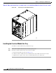
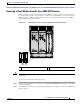
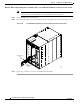
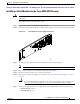
Clock modules are connected to the rear of the Cisco MDS 9509 Director using two connectors.
Figure 2-43 shows the clock modules in a rear view of the Cisco MDS 9509 Director with the back panel
removed.
Figure 2-43 Clock Module Location on the Cisco MDS 9509 Director (Rear View)
Ta b l e 2-6 Contents of Cisco MDS 9509 Clock Module Replacement Kits
Quantity Part Description
1 Cisco MDS 9509 clock module
12 M3 x 6-mm Phillips pan-head screws
1 Disposable ESD wrist strap
Cisco MDS 9509
1
2
120141