
Network Device Installation Guide

Send documentation comments to mdsfeedback-doc@cisco.com.
2-66
Cisco MDS 9500 Series Hardware Installation Guide
OL-17467-02
Chapter 2 Installing the Cisco MDS 9500 Series
Removing and Installing a Power Supply or PEM
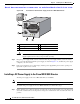
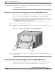
Installing an AC PEM
To install an AC PEM in a Cisco MDS 9506 chassis, follow these steps:
Step 1 Ensure that the system (earth) ground connection has been made. See the “System Grounding” section
on page 2-17.
Step 2 If a filler panel is installed, remove it from the PEM bay by loosening the captive screws and pulling it
from the chassis.
Step 3 Slide the PEM into the PEM bay, ensuring that the PEM is fully seated in the bay.
Step 4 Tighten the PEM captive screws to 8 in-lb.
Step 5 Provide power to the PEM as described in the “Providing Power to an AC Power Supply for the Cisco
MDS 9509 and Cisco MDS 9506 Directors” section on page 2-30.
Caution In a system with dual power supplies, connect each power supply to a separate power source.
In case of a power source failure, the second source will most likely still be available.
Step 6 Verify PEM and power supply operation by checking the power supply LED states in the back of the
chassis:
• INPUT OK LED is green.
• FAN OK LED is green.
• OUTPUT FAIL LED is off.
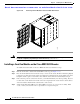
Installing a DC PEM
To install a DC PEM in a Cisco MDS 9506 chassis, follow these steps:
Step 1 Ensure that the system (earth) ground connection has been made. See the “System Grounding” section
on page 2-17.
Step 2 If a filler panel is installed, remove it from the PEM bay by loosening the captive screws and pulling it
from the chassis.
Step 3 Attach the DC power cables to the PEM as described in “Providing Power to a DC Power Supply in the
Cisco MDS 9506 Director” section on page 2-34.
Step 4 Slide the PEM into the PEM bay, ensuring that the PEM is fully seated in the bay.
Step 5 Tighten the PEM captive screws to 8 in-lb.
Caution In a system with dual power supplies, connect each power supply to a separate power source.
In case of a power source failure, the second source will most likely still be available.
Step 6 Verify PEM and power supply operation by checking the power supply LED states in the back of the
chassis:
• INPUT OK LED is green.
• FAN OK LED is green.