
Network Device Installation Guide

Send documentation comments to mdsfeedback-doc@cisco.com.
2-65
Cisco MDS 9500 Series Hardware Installation Guide
OL-17467-02
Chapter 2 Installing the Cisco MDS 9500 Series
Removing and Installing a Power Supply or PEM
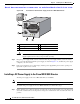
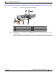
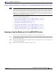
Figure 2-35 Connecting or Disconnecting the DC PEM
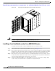
Step 4 If the PEM bay is to remain empty, install a PEM filler panel over the opening and tighten the captive
screws to 8 in-lb.
1 PEM terminal block screws (+ and -) 4 Stripped portion of positive cable
2 Captive screw 5 Insulated portion of negative cable
3 Ring lug
99293
( ) ( )
2
3
4
1
5
( )
( )